Light-emitting device and backlight module

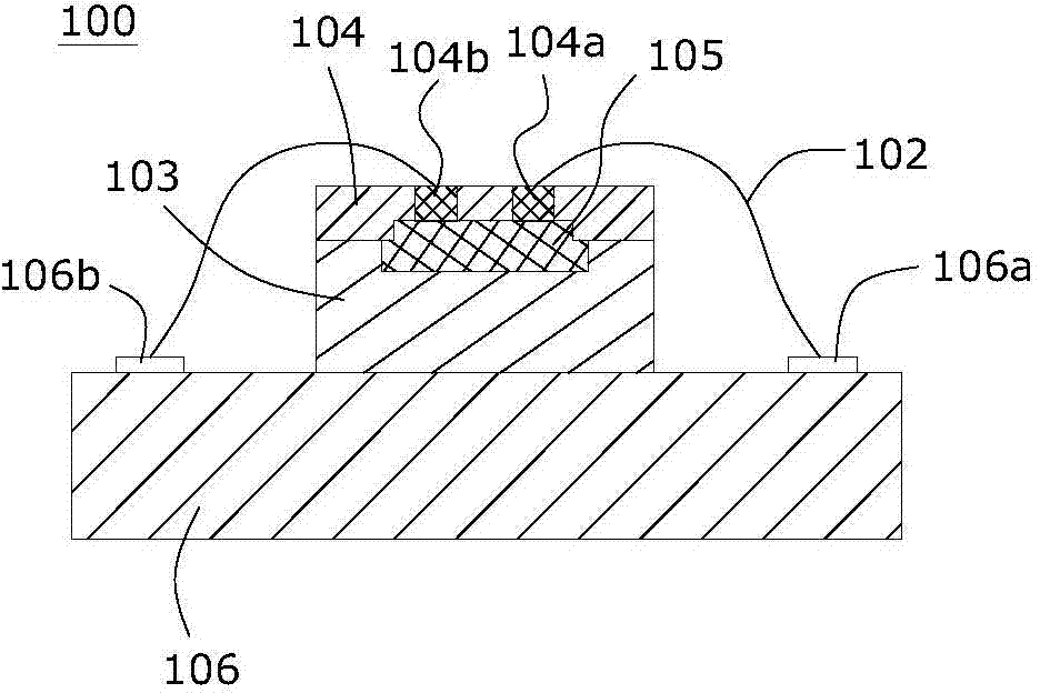
A light-emitting device and fluorescent layer technology, applied in optics, nonlinear optics, instruments, etc., can solve the problems of reducing the brightness and uniformity of the light-emitting device 100, and achieve the effects of simple structure, safe and reliable use, and improved brightness and uniformity

Active Publication Date: 2015-06-17
SHENZHEN CHINA STAR OPTOELECTRONICS TECH CO LTD +1
View PDF6 Cites 2 Cited by
  • Summary
  • Abstract
  • Description
  • Claims
  • Application Information

AI Technical Summary

Problems solved by technology

[0004] However, since the terminals 104a, 104b and the wire 102 are located above the LED chip 105, the terminals 104a and 104b and the wire 102 can block the light of the LED chip 105 when the LED chip emits light, reducing the brightness and uniformity of the light emitting device 100.

Method used


Image

  • Light-emitting device and backlight module
  • Light-emitting device and backlight module
  • Light-emitting device and backlight module

Examples


Embodiment Construction

[0022] The present invention will be further described below in conjunction with accompanying drawing.

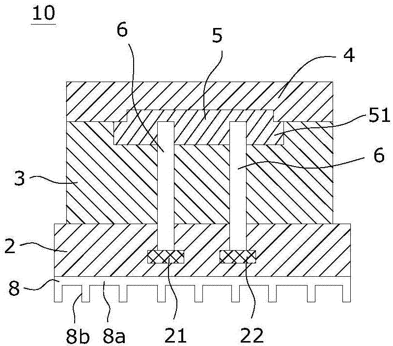
[0023] figure 2 There is shown a light emitting device 10 provided according to the first aspect of the invention. The light emitting device 10 includes a substrate 2 . The substrate 2 can be made of hard insulating material, such as ceramic material. The base plate 2 has two first pole legs 21 and a second pole leg 22 spaced apart from each other. These two pole legs are preferably made of metal materials, so as to be used for connecting to a power source and realizing the transmission of electric energy.

[0024] Meanwhile, the light emitting device 10 also includes a reflective layer 3 disposed on the upper surface of the substrate 2 . The reflective layer 3 can be made of a material with good reflective performance, which belongs to the prior art. The reflective layer 3 is used to reflect the light of the LED chip, so that most of the light is emitted toward the t...


PUM


Abstract

The invention relates to a light-emitting device and a backlight module. The light-emitting device comprises a substrate provided with a first electrode pin and a second electrode pin, a reflecting layer arranged on the upper surface of the substrate, a fluorescent layer arranged on the upper surface of the reflecting layer, and an LED chip embedded between the reflecting layer and the fluorescent layer. The LED chip is connected with the first electrode pin and the second electrode pin through two wires penetrating through the reflecting layer respectively. According to the light-emitting device, it can be avoided that light rays of the LED chip are shielded by terminals and the wires, and thus the brightness and the evenness of the light-emitting device can be improved.

Description

technical field [0001] The invention relates to a light-emitting device using an LED chip and a backlight module including the light-emitting device. Background technique [0002] The LED light source is called the fourth generation light source. It has the advantages of energy saving, environmental protection, safety and reliability, long life, low power consumption, high brightness, waterproof, miniature, shockproof, easy dimming, concentrated beam, and easy maintenance. It is widely used in various fields. Various indications, displays, decorations, backlights, general lighting and other fields. Backlight modules of LED light sources are widely used in liquid crystal displays. With the development of liquid crystal displays, LED light sources are constantly required to have higher brightness. [0003] figure 1 A typical light emitting device 100 in the prior art is shown, and the light emitting device 100 includes: a substrate 106 having a first pole pin 106a and a seco...

Claims


Application Information

Patent Timeline
Patent Type & Authority Applications(China)
IPC IPC(8): H01L33/64H01L33/62H01L33/60H01L33/50H01L33/48
CPCH01L33/48H01L33/50H01L33/60H01L33/62H01L33/64G02F1/1336
Inventor 周革革
Owner SHENZHEN CHINA STAR OPTOELECTRONICS TECH CO LTD
Why Eureka
Try Eureka