Plane horn antenna capable of achieving gap embedding amplitude calibration

A horn antenna and amplitude calibration technology, which is applied to antennas, waveguide horns, electrical components, etc., can solve the problems of uneven amplitude, low gain of horn antenna, and increase the overall structure size of the antenna, so as to increase the aperture efficiency and gain, and avoid the amplitude. Non-uniform, consistency-enhancing effects

Inactive Publication Date: 2015-06-17
SOUTHEAST UNIV
View PDF5 Cites 1 Cited by
  • Summary
  • Abstract
  • Description
  • Claims
  • Application Information

AI Technical Summary

Problems solved by technology

The substrate integrated waveguide planar horn antenna based on the substrate integrated waveguide not only has the characteristics of the horn antenna, but also realizes the miniaturization and light weight of the horn antenna, and is easy to integrate in the microwave millimeter wave planar circuit, but the traditional The gain of the substrate integrated waveguide planar horn antenna is relatively low. One of the important reasons is that the amplitude of the electromagnetic field on the horn aperture surface is very uneven, and the center is large and the two sides are small, which affects the aperture efficiency and radiation performance of the antenna.
At present, methods such as dielectric loading and dielectric prism have been used to correct the asynchronous phase of the horn aperture field, but these methods cannot improve the uniformity of the electromagnetic field amplitude distribution on the aperture surface, and these phase alignment structures increase the overall structural size of the antenna.

Method used


Image

  • Plane horn antenna capable of achieving gap embedding amplitude calibration
  • Plane horn antenna capable of achieving gap embedding amplitude calibration

Examples


Embodiment Construction

[0019] The present invention will be further described below in conjunction with drawings and embodiments.

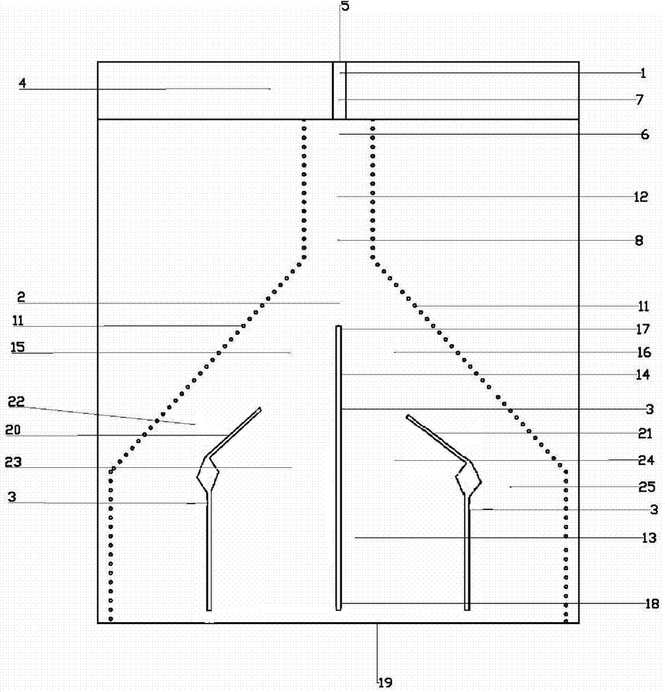
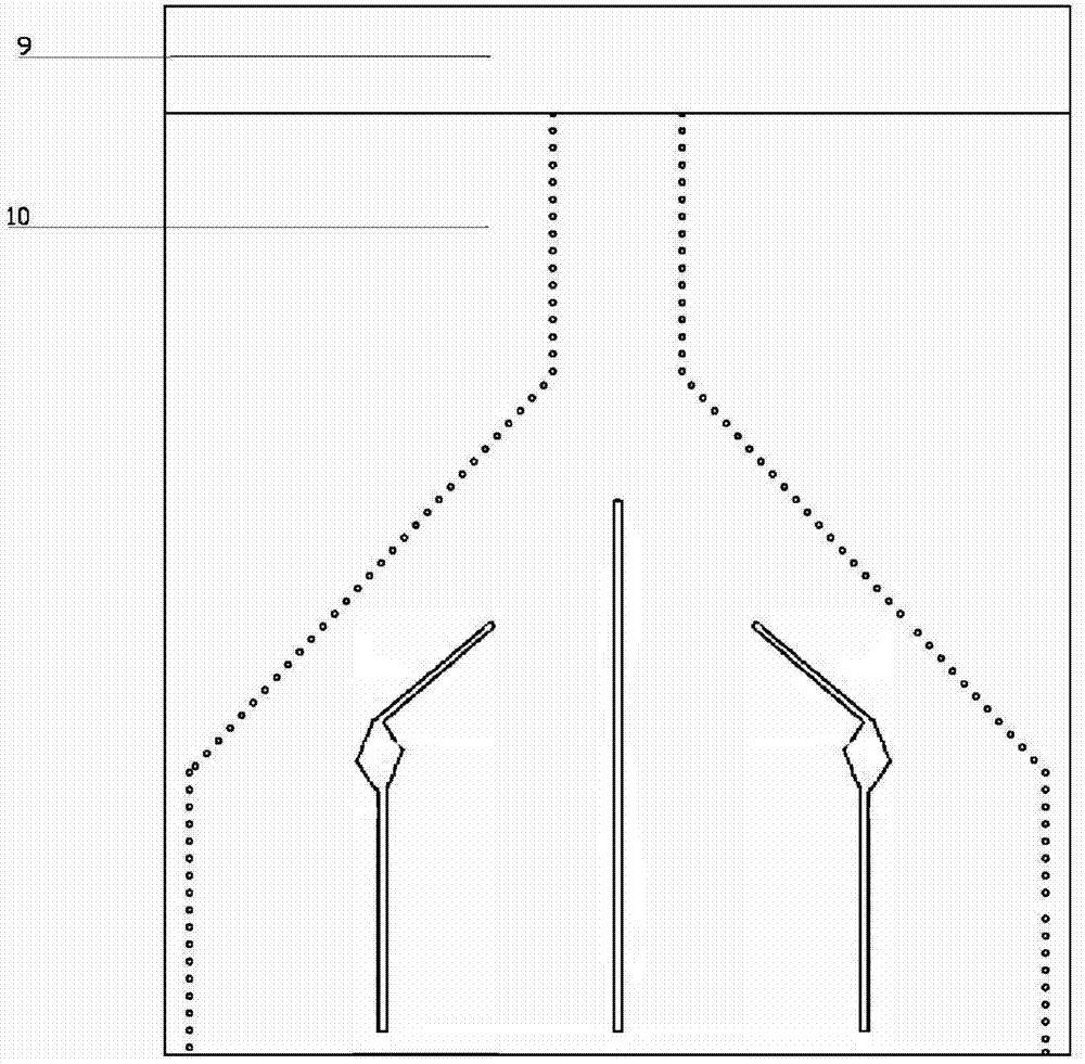
[0020] The embodiment that the present invention adopts is: the planar horn antenna of slit embedded amplitude calibration comprises the microstrip feeder 1 that is arranged on the dielectric substrate 4, substrate integrated waveguide horn antenna 2 and slit 3; One end of described microstrip feeder 1 is the input and output port 5 of the antenna, and the other end of the microstrip feeder 1 is connected to the narrow port 6 of the substrate integrated waveguide horn antenna 2; The second metal plane 10 located on the other side of the dielectric substrate 4 is composed of two rows of metallized via hole horn sidewalls 11 passing through the dielectric substrate 4 to connect the first metal plane 8 and the second metal plane 10; the first metal plane 8 and the second metal plane There are many slits 3 on the two metal planes 10 and form the middle slit 14, the left sli...


PUM


Abstract

The invention relates to a horn antenna, in particular to a plane horn antenna capable of achieving gap embedding amplitude calibration. The antenna comprises a micro-strip feeder line (1), a horn antenna body (2) and gaps (3), wherein the micro-strip feeder line (1), the horn antenna body (2) and the gaps (3) are integrated on a dielectric substrate (4). The micro-strip feeder line (1) is connected with an antenna port (5) and an antenna narrow port (6). The horn antenna body (2) is composed of a first metal plane (8), a second metal plane (10) and two rows of metallization via hole horn side walls (11), four sub-horns are formed in the horn antenna body (2) through the middle gap (14), the left gap (20) and the right gap (21) forming the gaps (3), one ends of the four sub-horns are close to the antenna narrow port (6), and the other ends of the four sub-horns are close to but no reach an antenna aperture face (19). The aperture efficiency and the gain of the antenna can be improved.

Description

technical field [0001] The invention relates to a planar horn antenna, in particular to a planar horn antenna with embedded amplitude calibration in a slot. Background technique [0002] Horn antennas are widely used in systems such as satellite communications, ground microwave links, and radio telescopes. However, the larger geometric size of the three-dimensional horn antenna and the incompatibility with the planar circuit process make its cost higher, thus limiting the development of its application. In recent years, the proposal and development of substrate-integrated waveguide technology have greatly promoted the development of planar horn antennas. The substrate-integrated waveguide has the advantages of small size, light weight, easy planar integration and simple processing. The substrate integrated waveguide planar horn antenna based on the substrate integrated waveguide not only has the characteristics of the horn antenna, but also realizes the miniaturization and...

Claims


Application Information

Patent Timeline
IPC IPC(8): H01Q13/02H01Q3/28
Inventor 赵洪新陈飞殷晓星
Owner SOUTHEAST UNIV
Why Eureka
Try Eureka