
Methods and systems for devolatilization of thermally produced liquids

A devolatilization and liquid technology, applied in liquid degassing, chemical instruments and methods, separation methods, etc.

Active Publication Date: 2015-06-17
ENSYN RENEWABLES
View PDF13 Cites 2 Cited by
  • Summary
  • Abstract
  • Description
  • Claims
  • Application Information

AI Technical Summary

Problems solved by technology

Therefore, low flash point measurements may unreasonably classify these liquids for flammability since the measurements reflect the flash point of only a small fraction of the total product

Method used


Image

  • Methods and systems for devolatilization of thermally produced liquids
  • Methods and systems for devolatilization of thermally produced liquids
  • Methods and systems for devolatilization of thermally produced liquids

Examples


Embodiment Construction

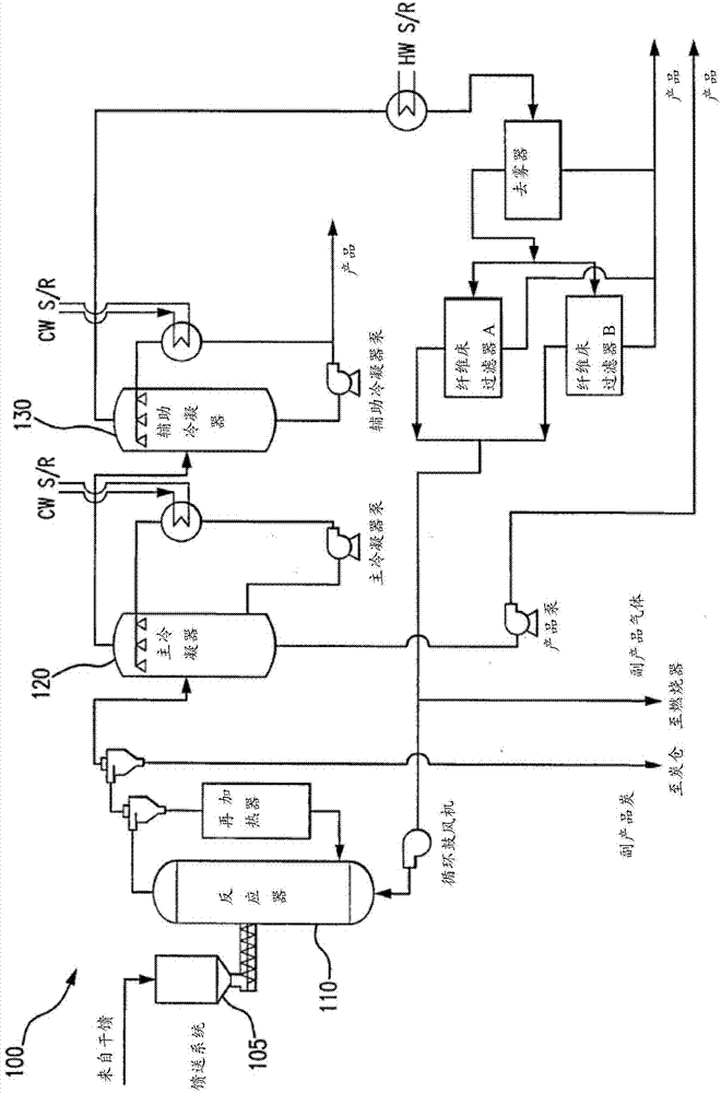
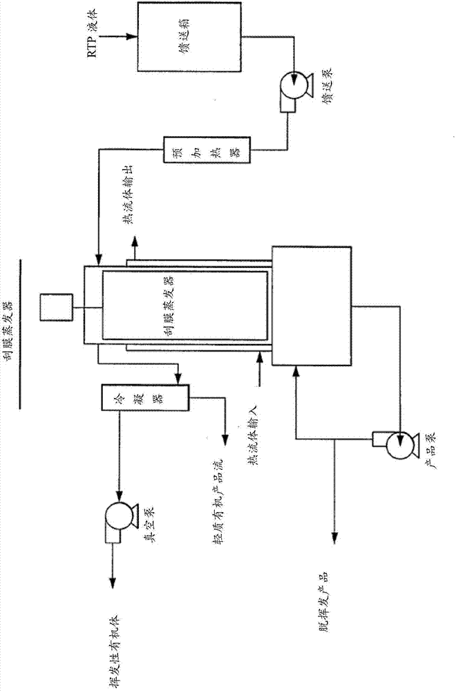
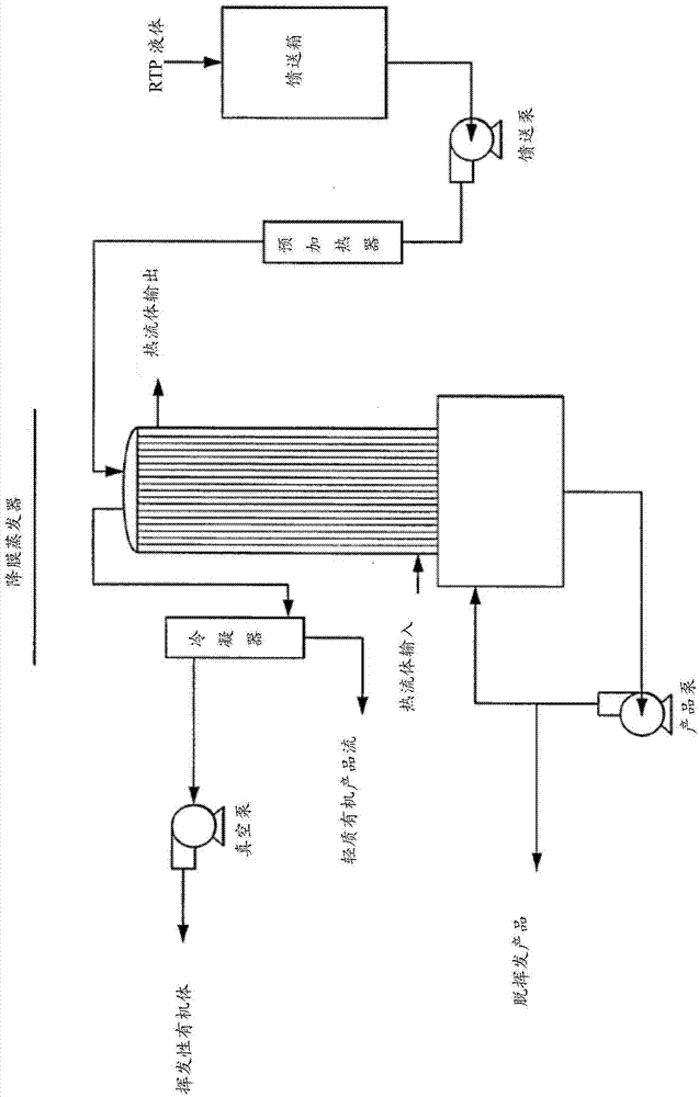
[0031]The present disclosure generally relates to the devolatilization of thermal liquids to increase the flash point. More specifically, the present disclosure is directed to methods and apparatus for effectively and selectively reducing the volatile content of liquids produced from thermal conversion of biomass and petroleum materials, thereby causing an increase in flash point.

[0032] A measure of the flash point of a liquid is a common measure of flammability and is indicated by the maximum temperature at which the material can be stored and handled. If the flash point is too low, it renders the liquid susceptible to flash and possible ignition. Certain properties of materials are generally not affected by changes in flash point, such as autoignition temperature, fuel injection, and combustion behavior. In many jurisdictions, there are significant differences in how materials are handled when their flashpoints are below a certain threshold. This threshold is typically ...


PUM

PropertyMeasurementUnit
flash pointaaaaaaaaaa

Abstract

Methods and systems for the devolatilization of thermally produced liquids to raise the flash point are disclosed. Various methods and apparatus can be used to effectively reduce the volatile components, such as wiped film evaporator, falling film evaporator, flash column, packed column, devolatilization vessel or tank.

Description

[0001] Cross References to Related Applications [0002] This application claims priority to US Provisional Application No. 61 / 693,156, filed August 24, 2012. The aforementioned related application is hereby incorporated by reference in its entirety. [0003] This disclosure relates to US Patent No. 7,572,362, US Patent No. 7,572,362, US Patent No. 7,270,743, US Patent No. 8,105,482, US Patent No. 8,062,503, US Patent No. 7,905,990, US Patent No. 8,097,090, and US Patent No. 5,792,340. U.S. Patent No. 7,572,365, U.S. Patent No. 7,572,362, U.S. Patent No. 7,270,743, U.S. Patent No. 8,105,482, U.S. Patent No. 8,062,503, U.S. Patent No. 7,905,990, U.S. Patent No. 8,097,090, and U.S. Patent No. 5,792,340 are incorporated by reference in their entirety incorporated into this article. technical field [0004] The present disclosure generally relates to the devolatilization of thermally produced liquids to increase the flash point. More specifically, the present disclosure is dire...

Claims


Application Information

Patent Timeline
Patent Type & Authority Applications(China)
IPC IPC(8): B01D3/06B01D19/00
CPCC10G55/04C10G2300/304C10L1/02C10G7/06C10G7/02C10L1/1802Y02E50/10Y02E50/30
Inventor 杰弗瑞·霍普金斯巴里·A·弗里尔道格·克拉克
Owner ENSYN RENEWABLES
Learn More