Milling machine

A milling machine and spindle technology, applied in the field of milling machines, can solve the problem that the depth of the spindle cannot be visually and accurately seen and set.

Inactive Publication Date: 2015-06-24
GAOYOU YONGFA MACHINERY
View PDF4 Cites 3 Cited by
  • Summary
  • Abstract
  • Description
  • Claims
  • Application Information

AI Technical Summary

Problems solved by technology

[0003] The purpose of the present invention is to provide a milling machine with an intuitive spindle feed depth, which solves the problem that the spindle depth of the existing milling machine cannot be seen and set intuitively and accurately

Method used


Image

  • Milling machine
  • Milling machine

Examples


Embodiment Construction

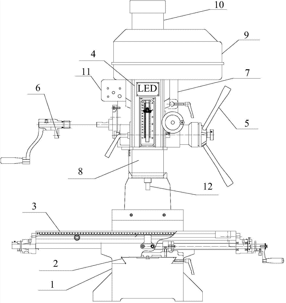
[0013] Such as figure 1 As shown, the present invention provides a milling machine, including a base 1, a cross carriage 2, a workbench 3, a spindle lifting handle 5, a spindle box lifting handle 6, a spindle box 7, a spindle 8, a pulley shield 9, a column 10, Motor 11, milling head 12. There is a dovetail between the base 1 and the cross carriage 2, the workbench 3 and the upper part of the cross carriage 2 are connected by a dovetail, the lower part of the column 10 is connected with the base 1 by four screws, the headstock 7 is located on the upper part of the column 10, and the motor 11 is installed On the motor plate located on the outside of the headstock.

[0014] Three belt pulleys are housed in pulley guard 9 inside, main shaft 8 is installed with main shaft box 7 inside, is connected with milling head 12 on main shaft 8, and motor 11 drives main shaft 8 by the transmission of belt pulley thereby controls milling head work.

[0015] Shaking the spindle box lifting h...


PUM


Abstract

The invention provides a milling machine and belongs to the field of mechanical equipment. By adoption of the milling machine, the problems that the value of the main-shaft feeding depth of an existing milling machine can not be seen intuitively and is not accurate are solved. The milling machine mainly comprises a base, a cross-shaped towing plate, a working platform, a main-shaft lifter, a main-shaft box lifter, a main-shaft box, a main shaft, a belt-wheel protective cover, a vertical column, a motor and a milling head. The milling machine provided by the invention has the advantages that due to adoption of a digital display ruler, the scale values can be intuitively seen, accurate positioning of the feeding depth can be realized and a product with high accuracy requirement can be processed.

Description

technical field [0001] The invention relates to mechanical pressure processing equipment, in particular to a milling machine. Background technique [0002] Milling machine is an indispensable general-purpose equipment in the machinery manufacturing industry, and it is also a high-yield machine tool in the machine tool industry. A milling machine is a machine tool that mainly uses a milling cutter to process various surfaces on a workpiece. The existing milling machine includes a base, a workbench, a column, a vertical slide plate that can be lifted up and down relative to the column, and a milling head seat arranged on the vertical slide plate. The spindle feed scale used by the existing milling machine is a digital scale. It cannot be seen intuitively when setting the feed value, and it is not accurate enough. In order to solve the above-mentioned shortcomings in the prior art, the present invention proposes a new technical solution to solve the above-mentioned problems. ...

Claims


Application Information

Patent Timeline
Patent Type & Authority Applications(China)
IPC IPC(8): B23C1/06B23C9/00
CPCB23C1/06B23C9/00
Inventor 邹建安朱恩权
Owner GAOYOU YONGFA MACHINERY
Why Eureka
Try Eureka