Stirring friction connecting device capable of reducing deformation and removing flashes

A technology of friction stirring and connecting devices, which is applied in welding equipment, non-electric welding equipment, metal processing, etc., can solve problems such as the distance between the fixture and the weld seam, poor butt joint, warping, etc., so as to reduce milling work and improve constraints , reduce the effect of secondary deformation

Inactive Publication Date: 2015-06-24
LINYI UNIVERSITY
View PDF7 Cites 11 Cited by
  • Summary
  • Abstract
  • Description
  • Claims
  • Application Information

AI Technical Summary

Problems solved by technology

[0005] In the process of friction stir welding of thin plates (thickness less than 2mm), because the plate is too thin, it is not easy to fix, especially at the joint of two plates, due to the interference between the position of the clamp and the stirring head, the distance between the clamp and the weld is relatively far, so in During the welding process, it is easy to have poor butt joint or warpage, which seriously affects the welding quality

Method used


Image

  • Stirring friction connecting device capable of reducing deformation and removing flashes
  • Stirring friction connecting device capable of reducing deformation and removing flashes
  • Stirring friction connecting device capable of reducing deformation and removing flashes

Examples


Embodiment 1

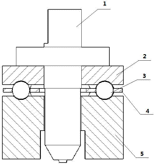
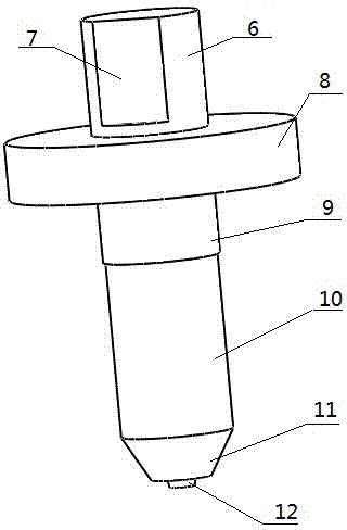
[0032] to combine figure 1 and figure 2 Describe the implementation process. In this embodiment, the thickness of the workpiece to be welded is 2mm, the length of the stirring needle is 1.5mm, the amount of pressure during welding is 2mm, the vertical distance between the sleeve and the shaft shoulder is 0.5mm, the outer diameter of the sleeve is 65mm, and the inner diameter is 20mm, the thickness of the sleeve is 22.5mm. The height of the sleeve is 33.5mm. During the welding process, the stirring head, the large cylinder (8) and the bearing block (2) rotate around the axis, but the sleeve (5) does not rotate. After the welding starts, the workpiece moves at a constant speed in a certain direction , the sleeve (5) compresses the workpiece through the downward pressure transmitted by the pressure block (2), realizing the vertical constraint. After the welding starts, all the surrounding areas to be welded are fixed to ensure the smoothness of the welding process. In the la...

Embodiment 2

[0034] to combine figure 1 and figure 2Describe the implementation process. In this embodiment, the thickness of the workpiece to be welded is 1mm, the length of the stirring needle is 0.8mm, the amount of pressure during welding is 1mm, the vertical distance between the sleeve and the shaft shoulder is 0.2mm, the outer diameter of the sleeve is 65mm, and the inner diameter is 20mm, the thickness of the sleeve is 22.5mm. The height of the sleeve is 33.2mm. During the welding process, the stirring shaft (1), the large cylinder (8), and the pressure block (2) rotate around the axis, and the sleeve (5) does not rotate. After the welding starts, the workpiece moves along a certain direction Moving at a constant speed, the sleeve (5) presses the workpiece through the downward force transmitted by the pressure block (2) to achieve vertical restraint. After the welding starts, all the surrounding areas to be welded are fixed to ensure the smoothness of the welding process. At th...


PUM


Abstract

The invention relates to a stirring friction connecting device capable of reducing workpiece deformation and removing flashes. The stirring friction connecting device is composed of a stirring shaft (1), a pressure block (2), roller retainers (3), rollers (4) and a sleeve (5). The sleeve (5) achieves moving and restraining effects on a workpiece through downward pressing force transmitted by the pressure block (2), so that it is guaranteed that the workpiece can be restrained at the optimal state at every moment in the welding process, and workpiece deformation is effectively reduced; in addition, in the downward pressing process of the sleeve (5), the flashes generated in the welding process can be effectively removed, and the subsequent milling process is simplified.

Description

technical field [0001] The invention relates to a friction stir joining device capable of reducing deformation and removing burrs, especially for butt welding of thin plates (<=2mm), which can effectively prevent plate deformation and remove burrs during welding, which belongs to material connection technology field. Background technique [0002] Friction stir welding (FSW) was invented by The Welding Institute (TWI) in 1991. It is a new solid phase joining technology with the patent number (US 5460317). When welding with this technology, stirring The head rotates at a constant speed and moves at a constant speed according to the set trajectory. The stirring needle is inserted into the material for stirring, and the strong friction between the shoulder of the stirring head and the base material makes the metal material in the heat-affected zone in a solid solution state. , the maximum temperature of the base metal does not exceed the melting point, under the joint action...

Claims


Application Information

Patent Timeline
Patent Type & Authority Applications(China)
IPC IPC(8): B23K20/12B23K20/26
CPCB23K20/1255B23K2101/185
Inventor 李信利
Owner LINYI UNIVERSITY
Why Eureka
Try Eureka