Cutter wear monitoring method based on current and acoustic emission compound signals

A technology of acoustic emission signals and tool wear, which is applied in the field of tool wear monitoring based on current and acoustic emission composite signals, can solve the problems of low stability and reliability of acoustic emission signal monitoring

Active Publication Date: 2015-06-24
艾维克(沈阳)新工艺科技开发有限责任公司
View PDF5 Cites 40 Cited by
  • Summary
  • Abstract
  • Description
  • Claims
  • Application Information

AI Technical Summary

Problems solved by technology

Although the features extracted by the above methods can reflect the wear state of the tool to a certain extent, due to the complexity of the actual processing conditions, these featur...

Method used


Image

  • Cutter wear monitoring method based on current and acoustic emission compound signals
  • Cutter wear monitoring method based on current and acoustic emission compound signals
  • Cutter wear monitoring method based on current and acoustic emission compound signals

Examples


Embodiment Construction

[0061] The present invention will be further elaborated below in combination with specific embodiments.

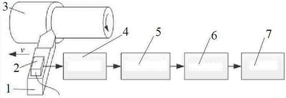
[0062] The detection principle of the acoustic emission (Acoustic Emission, AE) signal that reflects the wear state of the turning tool proposed by the present invention is as follows: figure 1 As shown: the acoustic emission sensor 2 is directly installed on the handle of the turning tool 1 to reduce the large attenuation of the acoustic emission signal when it propagates between the joint surfaces. The acoustic emission signal generated by the turning tool 1 during the cutting process passes through the signal successively Amplifier 4, anti-aliasing filter 5 and A / D converter I6 are stored in computer 7 for subsequent processing and analysis;

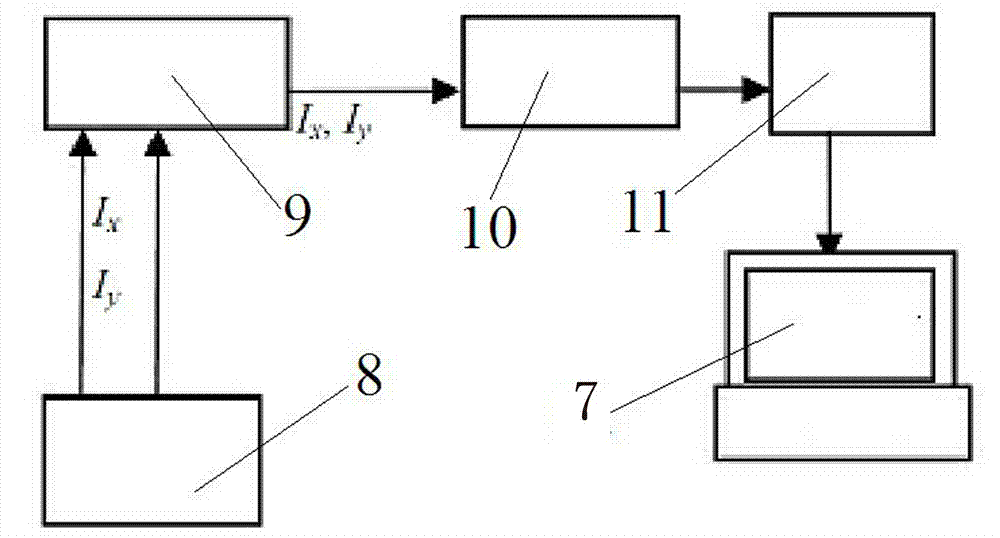
[0063] The described acoustic emission signal processing and analysis process is as follows:

[0064] The principle of tool wear state discrimination is as follows: figure 2 Indicates: under the same processing parameters, set...


PUM


Abstract

The invention relates to a cutter wear monitoring method based on current and acoustic emission compound signals. According to the cutter wear monitoring method, the current signal of a spindle motor and acoustic emission signals of a turning tool wear state in cutting machining are detected, processing and analyzing are conducted based on the current and acoustic emission compound signals, and then the wear state of a cutter is monitored in real time; the current signals of the cutting motor and the cutter wear state features in the acoustic emission signals are obtained in a self-adaptive mode, the abundant cutter wear state information in the current signals of the cutting motor and the acoustic emission compound signals are fully excavated, through a wavelet packet analysis method, a correlation analysis method, a principle compound analysis method and the like, the feature information reflecting the current wear state of the cutter is extracted in a self-adaptive mode, and the wear degree of the cutter is judged by analyzing the relevance between the feature information reflecting the current wear state and initial wear state features.

Description

technical field [0001] The invention relates to the field of tool wear monitoring, in particular to a tool wear monitoring method based on current and acoustic emission composite signals. Background technique [0002] As a part of the automation technology of the manufacturing process, tool wear status recognition has been increasingly valued by people. A reliable tool wear status monitoring system can guide the machine tool to complete automatic tool change by timely and accurately reflecting the tool wear status information to achieve uninterrupted The production process stabilizes the processing quality of the workpiece. [0003] Tool wear state monitoring methods are mainly divided into direct measurement method and indirect measurement method. Direct measurement methods, such as optical method, radiation method, resistance method, etc., have high measurement accuracy, but are susceptible to interference from the processing environment, making it inconvenient to perfor...

Claims


Application Information

Patent Timeline
IPC IPC(8): B23Q17/09
CPCB23Q17/0961B23Q2717/003
Inventor 李彬
Owner 艾维克(沈阳)新工艺科技开发有限责任公司
Why Eureka
Try Eureka