
Nut machining method

A processing method and nut technology, applied in metal processing equipment, manufacturing tools, grinding devices, etc., can solve problems such as insufficient rigidity, inability to maintain the forming grinding wheel 11, and decrease in grinding accuracy, and achieve high-precision effects

Active Publication Date: 2015-06-24
TBI MOTION TECH CO LTD
View PDF5 Cites 2 Cited by
  • Summary
  • Abstract
  • Description
  • Claims
  • Application Information

AI Technical Summary

Problems solved by technology

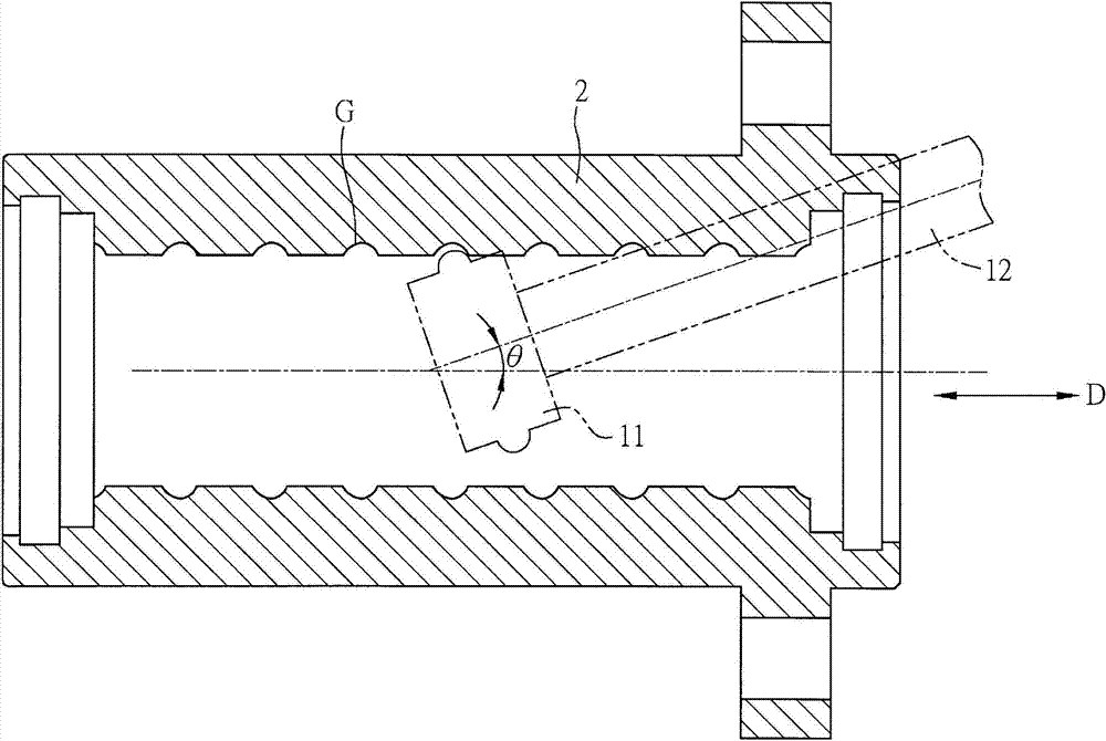
However, when the forming grinding wheel 11 is ground along the thread groove G, if the forming grinding wheel 11 vibrates, the grinding accuracy will decrease.
The vibration may be caused by the contact between the forming grinding wheel 11 and the nut 2, or the vibration caused by the lack of rigidity of the support rod 12 itself, which cannot maintain the stability of the forming grinding wheel 11 during rotation, or when the support rod 12 The included angle θ between the central axis of the nut 2 and the direction D in which the inner surface of the nut 2 extends is too large to cause vibrations caused by interference with the nut 2; the above conditions will make the grinding accuracy unable to meet the requirements

Method used


Image

  • Nut machining method
  • Nut machining method
  • Nut machining method

Examples


Embodiment Construction

[0023] The method for processing a nut according to a preferred embodiment of the present invention will be described below with reference to the relevant drawings, wherein the same elements will be described with the same reference symbols.

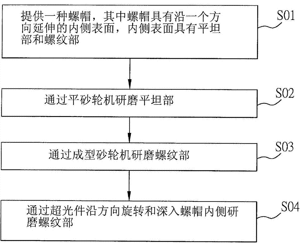
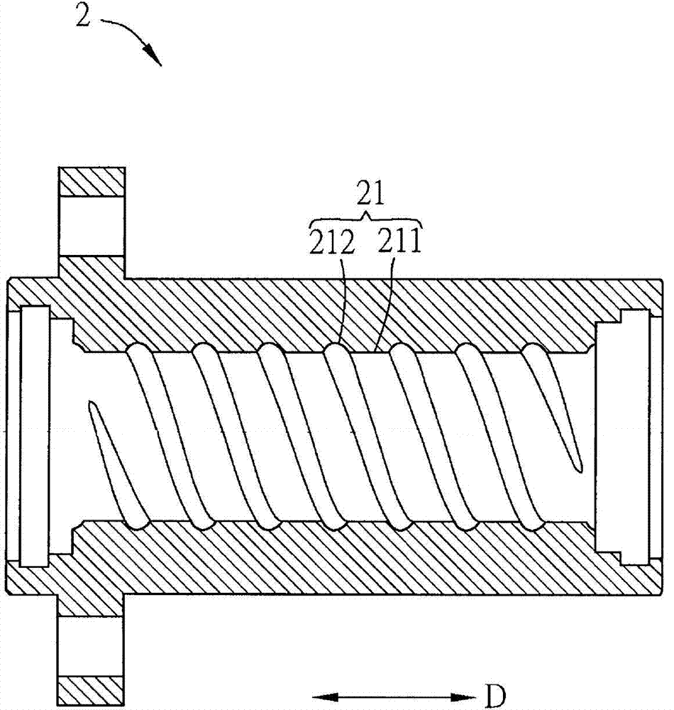
[0024] Please refer to figure 2 , Figure 3A to Figure 3D As shown, among them, figure 2 It is a schematic flow chart of a processing method for a nut in a preferred embodiment of the present invention, and Figure 3A is a schematic cross-sectional view of a nut 2, Figure 3B and Figure 3C Respectively is a schematic diagram of the processing process of a nut 2 of the preferred embodiment of the present invention, and Figure 3D for Figure 3C An enlarged schematic view of region A of .

[0025] The nut processing method of the present invention can be applied to nuts with a helix angle between 1 degree and 50 degrees. As shown in the figure, the processing method of the nut can be applied to grinding the nut 2 to make its prec...


PUM

PropertyMeasurementUnit
Helix angleaaaaaaaaaa

Abstract

The invention discloses a nut machining method. The nut machining method includes the steps of providing a nut, wherein the nut is provided with an inner surface extending along a direction, and the inner surface is provided with a flat portion and a threaded portion; grinding the flat portion by a flat grinder; grinding the threaded portion by a forming grinder; rotating a super polishing part along the direction to extend into the inner side of the nut so as to grind the threaded portion. The nut machining method can enable the machined threaded portion to be higher in precision.

Description

technical field [0001] The invention relates to a processing method for a nut. Background technique [0002] The ball screw is a device widely used in many mechanical equipment. Its purpose is to provide a precise transmission function, which can achieve linear motion in mechanical operation, and then make the loaded machine or object move in a linear direction. . Wherein, the ball screw mainly includes a screw, a nut and a plurality of balls, the balls are accommodated in the nut, and the nut is sleeved on the screw, so that the nut and the balls can move linearly relative to the screw. [0003] However, in the prior art, such as figure 1 As shown, in order to grind the thread of a nut 2 so that the thread groove G has high precision so that the screw can move smoothly relative to the nut 2, the forming grinding wheel 11 of the forming grinder is usually used to extend into the nut 2 The inner side is used to grind the thread groove G. However, when the shaped grinding ...

Claims


Application Information

Patent Timeline
IPC IPC(8): B24B37/00
CPCB23G9/008B23G2210/21
Inventor 李进胜杨进财
Owner TBI MOTION TECH CO LTD
Learn More