Sliding installation method for large span section steel beam

An installation method and a large-span technology, which are applied in the processing of building materials, construction, and building construction, etc., can solve the problems of large workload of synchronous control, short single-step sliding stroke, low efficiency, etc., and reduce construction costs. difficulty, long sliding stroke, and continuous construction work

Active Publication Date: 2015-06-24
CHINA CONSTR EIGHT ENG DIV CORP LTD
View PDF5 Cites 3 Cited by
  • Summary
  • Abstract
  • Description
  • Claims
  • Application Information

AI Technical Summary

Problems solved by technology

The traditional sliding method mostly adopts cluster jacks to be applied to both ends of the beam body, and multi-point synchronous pushing and sliding has defects such as difficulty, large amount of synchronization control input, short single-step sliding stroke, and low efficiency. Construction needs to be carried out in a larger site, and there is a higher requirement for the width of the site

Method used


Image

  • Sliding installation method for large span section steel beam
  • Sliding installation method for large span section steel beam
  • Sliding installation method for large span section steel beam

Examples


Embodiment Construction

[0053]In order to make the object, technical solution and advantages of the present invention clearer, the present invention will be further described in detail below in conjunction with the accompanying drawings and embodiments. It should be understood that the specific embodiments described here are only used to explain the present invention, not to limit the present invention.

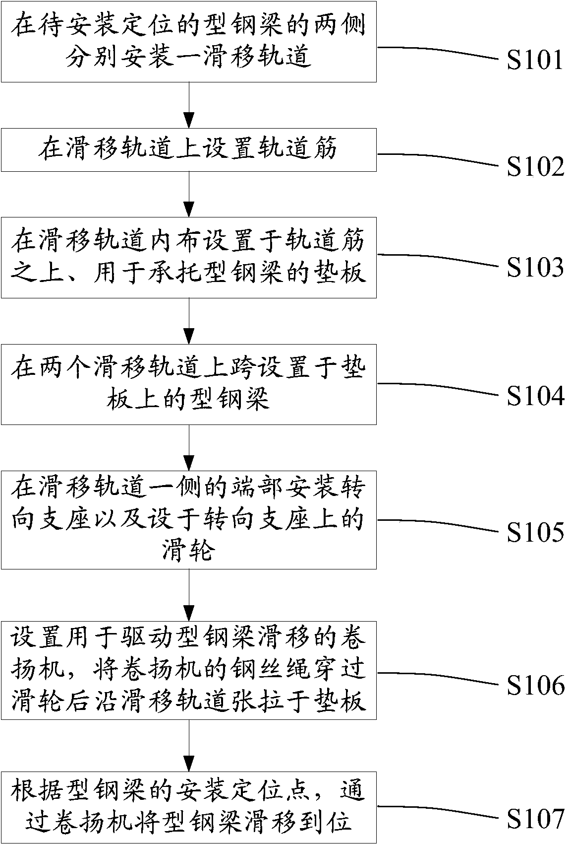
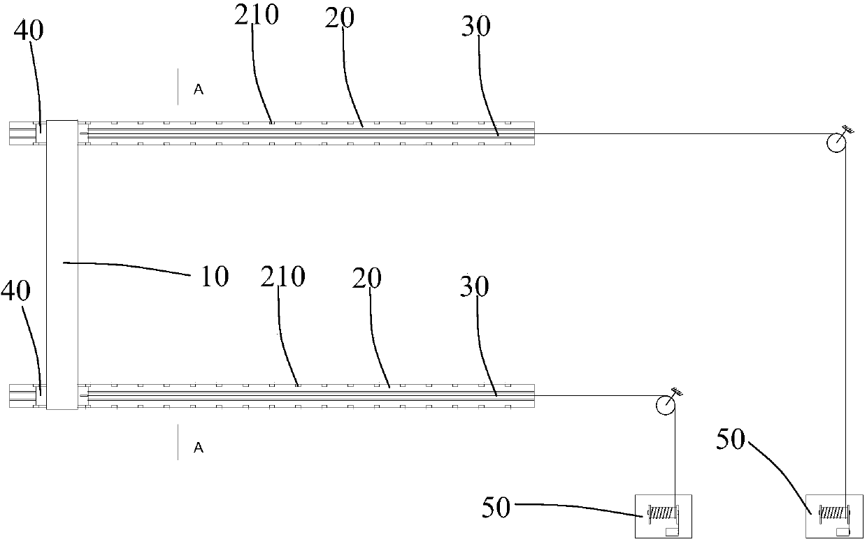
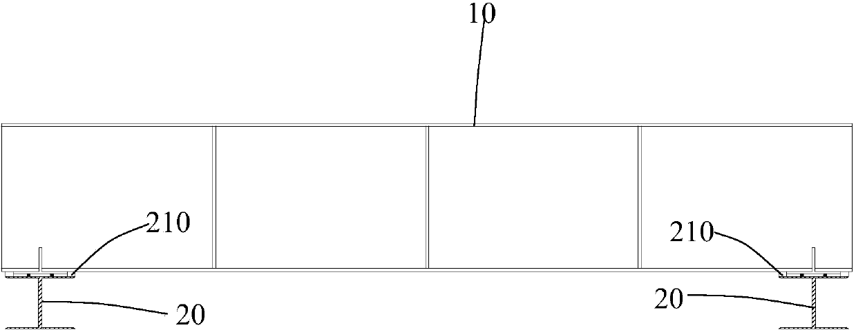
[0054] see Figure 1 ~ Figure 4 , figure 1 It is a flow chart of a sliding installation method for a large-span steel beam of the present invention, figure 2 It is a construction plan view of a sliding installation method for large-span steel beams of the present invention, image 3 for figure 2 The cross-sectional view of plane A-A in the middle, Figure 4 It is a structural schematic diagram of a steering support for a sliding installation method of a large-span steel beam according to the present invention. Cooperate with reference Figure 1 ~ Figure 4 As shown, a sliding installation met...


PUM


Abstract

The invention provides a sliding installation method for a large span section steel beam. The sliding installation method comprises the steps that two sliding rails are installed on the two sides of the section steel beam to be installed and positioned respectively; rail ribs are arranged on the sliding rails; base plates arranged on the rail ribs and used for bearing the section steel beam are arranged in the sliding rails; the section steel beam arranged on the base plates is arranged on the two sliding rails in a span mode; turning supports and pulleys arranged on the turning seats are installed at the ends of one sides of the sliding rails; winches used for driving the section steel beam to slide are arranged, and steel wire ropes of the winches penetrate through the pulleys and then are tensioned to the base plates along the sliding rails; according to the installing and positioning points of the section steel beam, the section steel beam is slide in place through the winches. By means of the design of the turning supports and the pulleys, the steel wire ropes of the winches can be turned, the transverse and longitudinal space is fully used, and the difficulty that construction cannot be carried out due to the insufficient longitudinal sliding length of a roof is overcome.

Description

technical field [0001] The invention relates to the technical field of building construction, in particular to a sliding installation method for large-span steel beams. Background technique [0002] At present, my country's theaters, cultural centers, and stadiums and other buildings all adopt long-span space structures with different shapes. In order to achieve sufficient weight for the floor structure, the required horizontal main girders need to use large-section steel girders to improve their overall performance. The spanning ability and carrying level. The traditional sliding method mostly adopts cluster jacks to be applied to both ends of the beam body, and multi-point synchronous pushing and sliding has defects such as difficulty, large amount of synchronization control input, short single-step sliding stroke, and low efficiency. Construction needs to be carried out in a larger site, and there is a higher requirement for the width of the site. Contents of the invent...

Claims


Application Information

Patent Timeline
Patent Type & Authority Applications(China)
IPC IPC(8): E04G21/14
Inventor 马明磊窦市鹏吕三权冯辉黄海王洪浩张博玮汪贵临章群刘骏杰尹福成王建姚鲁朱庆涛
Owner CHINA CONSTR EIGHT ENG DIV CORP LTD
Why Eureka
Try Eureka