Fuel switching device for multi-fuel combustion chamber of gas turbine and control device of fuel switching device

A gas turbine and switching device technology, which is used in gas turbine devices, fuel control of turbine/propulsion devices, jet propulsion devices, etc., can solve the problems of increased jet area and unqualified cooling of the flame tube wall, and achieves optimized design and reduced effective jet flow. Area, the effect of widening the safe working area

Active Publication Date: 2015-06-24
CHINA UNITED GAS TURBINE TECH CO LTD
View PDF6 Cites 9 Cited by
  • Summary
  • Abstract
  • Description
  • Claims
  • Application Information

AI Technical Summary

Problems solved by technology

In order to ensure that the fuel jet velocity at the nozzle head is in the proper range, the jet area required by the nozzle head is greatly increased, which requires a larger nozzle head size; and if the nozzle head size is too large, the amount of fuel coming out of the nozzle will It will be too close to the flame tube, which will lead to unqualified cooling of the wall of the flame tube

Method used


Image

  • Fuel switching device for multi-fuel combustion chamber of gas turbine and control device of fuel switching device
  • Fuel switching device for multi-fuel combustion chamber of gas turbine and control device of fuel switching device

Examples


Embodiment Construction

[0032] Embodiments of the present invention will be further described in detail below in conjunction with the accompanying drawings and examples. The following examples are used to illustrate the present invention, but should not be used to limit the scope of the present invention.

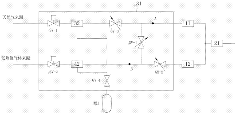
[0033] Such as figure 1 As shown, the gas turbine multi-fuel combustor fuel switching device of this embodiment is characterized in that it includes: a flame tube 21, a natural gas fuel channel 11, a syngas fuel channel 12 and a fuel pre-system 31; a natural gas fuel channel 11 and a syngas The fuel passages 12 are connected in parallel, and the outlets are all connected to the flame tube 21, and the inlets are respectively connected to the fuel pre-system 31;

[0034] The fuel pre-system 31 includes: a natural gas purge system 32 and a synthesis gas purge system 42; the inlet of the natural gas purge system 32 is connected to a natural gas source, and its outlet is connected to the inlet of the ...


PUM


Abstract

The invention relates to the technical field of gas turbines, and particularly discloses a fuel switching device for a multi-fuel combustion chamber of a gas turbine. The fuel switching device comprises a flame tube, a natural gas fuel channel, a synthesis gas fuel channel and a fuel front-end system, wherein the fuel front-end system comprises a natural gas purge system and a synthesis gas purge system; an inlet of the natural gas purge system is connected with a natural gas source; the outlet of the natural gas purge system is connected with the inlet of the natural gas fuel channel; the inlet of the synthesis gas purge system is connected with a medium and low heat value gas source; the outlet of the synthesis gas purge system is connected with the inlet of the synthesis gas fuel pipeline; a natural gas pressure-stabilizing valve is arranged at the upstream of the natural gas purge system; a third control valve is arranged at the downstream of the natural gas purge system; a synthesis gas pressure-stabilizing valve is arranged at the upstream of the synthesis gas purge system; a second control valve is arranged at the downstream of the synthesis gas purge system; and a first control valve is arranged between the downstream of the third control valve and the upstream of the second control valve. According to the fuel switching device, the required effective jet area of the head part of a nozzle when a lot of synthesis gas is jet is effectively reduced.

Description

technical field [0001] The invention relates to the technical field of gas turbines, in particular to a gas turbine multi-fuel combustor fuel switching device and a control method thereof. Background technique [0002] For an IGCC combustor burning medium and low calorific value fuels, the volume flow rate of medium and low calorific value fuels is 10 times the volume flow rate of natural gas fuel, accounting for 10% to 20% of the total gas volume flow rate inside the combustion chamber. Such a large increase in volume flow rate will drastically change the flow field structure in the combustor head, thus posing a challenge to the design of the combustor nozzle. In order to ensure that the fuel jet velocity at the nozzle head is in the proper range, the jet area required by the nozzle head is greatly increased, which requires a larger nozzle head size; and if the nozzle head size is too large, the amount of fuel coming out of the nozzle will It will be too close to the flame...

Claims


Application Information

Patent Timeline
Patent Type & Authority Applications(China)
IPC IPC(8): F02C7/228F02C9/40F02C9/42
Inventor 李珊珊吕煊方子文王绥德
Owner CHINA UNITED GAS TURBINE TECH CO LTD
Why Eureka
Try Eureka