A positioning method, positioning device and positioning system

A positioning device and positioning method technology, applied in the electronic field, can solve the problems of unable to wipe the plate of APR02, time-consuming and laborious, APR02 being polluted, etc.

Inactive Publication Date: 2017-10-10
HEFEI BOE OPTOELECTRONICS TECH +1
View PDF6 Cites 1 Cited by
  • Summary
  • Abstract
  • Description
  • Claims
  • Application Information

AI Technical Summary

Problems solved by technology

[0004] However, in the above-mentioned printing process, the APR 02 may be polluted. At this time, there will be defective spots on the APR 02. Then, when the printing machine 100 prints the alignment film 03 to the substrate 04, it will cause the substrate 04 to be contaminated. Bad spots also appear on the corresponding positions of the bad spots on APR 02. Therefore, it is necessary to wipe the contaminated bad spots on APR 02 in time to ensure the printing quality of substrate 04.
[0005] At present, when determining the bad points on the APR 02, it mainly relies on the identification and judgment of the human eye. Obviously, this method of determining the bad points on the APR 02 is time-consuming and laborious, and cannot guarantee the accuracy of the bad points determined. Accuracy, and thus the APR 02 cannot be accurately wiped

Method used


Image

  • A positioning method, positioning device and positioning system
  • A positioning method, positioning device and positioning system
  • A positioning method, positioning device and positioning system

Examples


Embodiment 1

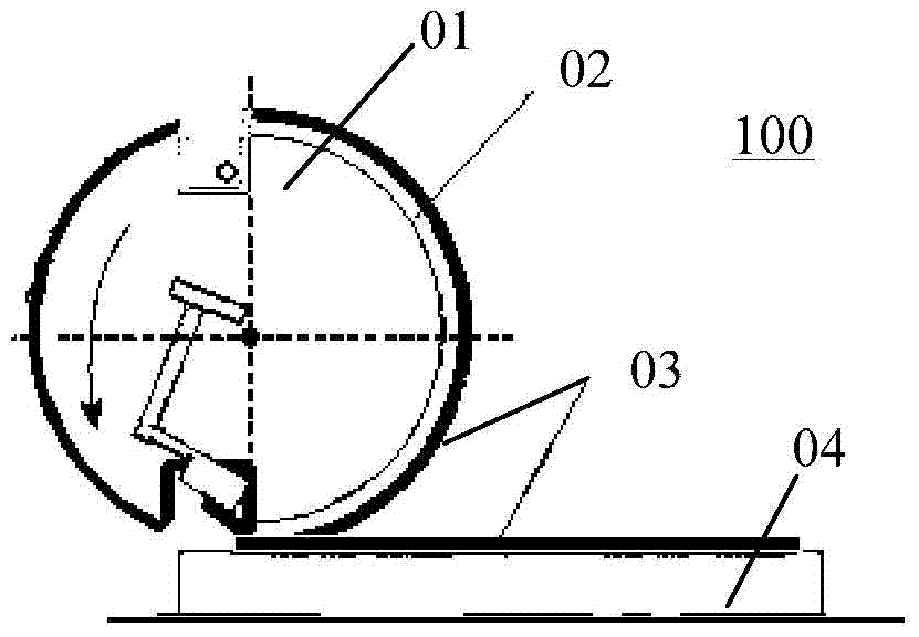
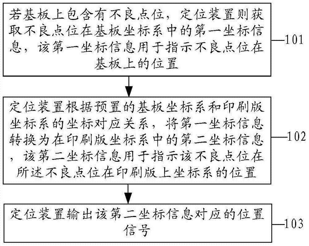
[0058] Embodiments of the present invention provide a positioning method, such as figure 2 shown, including:

[0059] 101. If the substrate contains defective spots, the positioning device acquires first coordinate information of the defective spots in the substrate coordinate system, where the first coordinate information is used to indicate the positions of the defective spots on the substrate.

[0060] 102. The positioning device converts the first coordinate information into second coordinate information in the printing plate coordinate system according to the preset coordinate correspondence between the substrate coordinate system and the printing plate coordinate system, and the second coordinate information is used to indicate the defect The position of the point on the printing plate.

[0061] 103. The positioning device outputs a position signal corresponding to the second coordinate information.

[0062] Specifically, the positioning method provided by the embodim...

Embodiment 2

[0074] Embodiments of the present invention provide a positioning method, such as Figure 4 shown, including:

[0075] 201. The positioning device establishes a coordinate correspondence between the substrate coordinate system and the printing plate coordinate system.

[0076] 202. If there are defective spots on the substrate, the positioning device acquires the image information of the defective spots on the substrate captured by the CCD lens.

[0077] 203. If the image information indicates that the defective spots on the substrate are caused by abnormal printing on the substrate, the positioning device receives a positioning instruction triggered by the user.

[0078] 204. The positioning device generates first coordinate information according to the positioning instruction, where the first coordinate information includes horizontal position coordinates and vertical position coordinates at the first coordinates.

[0079] 205. The positioning device converts the first coo...

Embodiment 3

[0094] Embodiments of the present invention provide a positioning device, such as Figure 5 shown, including:

[0095] A coordinate acquisition unit 51, configured to acquire first coordinate information of the defective point in the substrate coordinate system if the substrate contains a bad point, and the first coordinate information is used to indicate the bad point position on said substrate;

[0096] The coordinate conversion unit 52 is configured to convert the first coordinate information in the coordinate acquisition unit 51 into the second coordinate information in the printing plate coordinate system according to the preset coordinate correspondence between the substrate coordinate system and the printing plate coordinate system. Coordinate information, the second coordinate information is used to indicate the position on the printing plate corresponding to the defective point on the substrate;

[0097] The signal output unit 53 is configured to output a position s...


PUM


Abstract

The embodiment of the invention provides a positioning method, device and system, and relates to the technical field of electronics. The accuracy and efficiency of wiping a printing plate are improved. The scheme includes the steps that if a substrate comprises a bad point position, the positioning device obtains first coordinate information, in a substrate coordinate system, of the bad point position, and the first coordinate information is used for indicating the position, on the substrate, of the bad point position; according to the preset coordinate corresponding relation between the substrate coordinate system and a printing plate coordinate system, the positioning device converts the first coordinate information into second coordinate information in the printing plate coordinate system, and the second coordinate information is used for indicating the position, corresponding to the bad point position on the substrate, of the printing plate; the positioning device outputs a position signal, corresponding to the second coordinate information, on the printing plate. The scheme can be used for positioning the bad point position on the printing plate.

Description

technical field [0001] The invention relates to the field of electronic technology, in particular to a positioning method, a positioning device and a positioning system. Background technique [0002] Liquid Crystal Display (LCD) is mainly composed of an array substrate and a color film substrate. During the manufacturing process of a liquid crystal display, an alignment film needs to be printed on the array substrate or color film substrate by a printing machine, so that the liquid crystal molecules in the liquid crystal display arranged in a certain direction. [0003] Such as figure 1 As shown, the printing machine 100 specifically includes a plate barrel 01, an APR (Ashahikasei Photosensitive Resin, a resin plate for printing liquid crystal alignment film, also known as a printing plate) 02, and an alignment film 03 attached to the APR 02. The printing machine 100 is in the process of rotating The alignment film 03 is printed on the surface of the substrate 04 (array su...

Claims


Application Information

Patent Timeline
Patent Type & Authority Patents(China)
IPC IPC(8): G02F1/1337
CPCG02F1/1337G02F1/133354G02F1/133374
Inventor 刘聪聪金相旭张建政王平阳奇林强余涛
Owner HEFEI BOE OPTOELECTRONICS TECH
Why Eureka
Try Eureka