Display device and gate drive circuit and gate drive unit circuit thereof
A unit circuit and gate drive technology, applied in static indicators, instruments, etc., can solve the problems of short life of GOA, achieve long working life, and suppress the drift speed of threshold voltage
- Summary
- Abstract
- Description
- Claims
- Application Information
AI Technical Summary
Problems solved by technology
Method used
Image
Examples
Embodiment 1
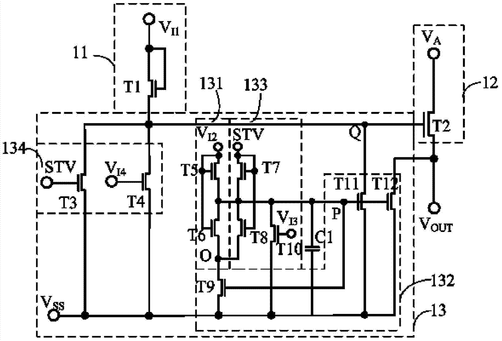
[0044] Please refer to figure 1 , this embodiment provides a gate driving unit circuit, including an input module 11 , a driving module 12 and a low level maintaining module 13 .
[0045] The input module 11 is coupled between the first pulse signal terminal and the first node Q, for responding to the first pulse signal V I1 The high level of the first node Q is charged.
[0046] The control terminal of the driving module 12 is used to be coupled to the first node Q, and its input terminal is used to input the first clock signal V A , whose output is used to couple to the signal output V OUT , the drive module 22 sends the first clock signal V A Applied to the signal output terminal V OUT .
[0047] The low level maintaining module 13 includes a first charging unit 131 and a threshold voltage self-compensating unit 132 .
[0048] The first charging unit 131 includes a fifth transistor T5 and a sixth transistor T6, the gate and the drain of the fifth transistor T5 are cou...
Embodiment 2
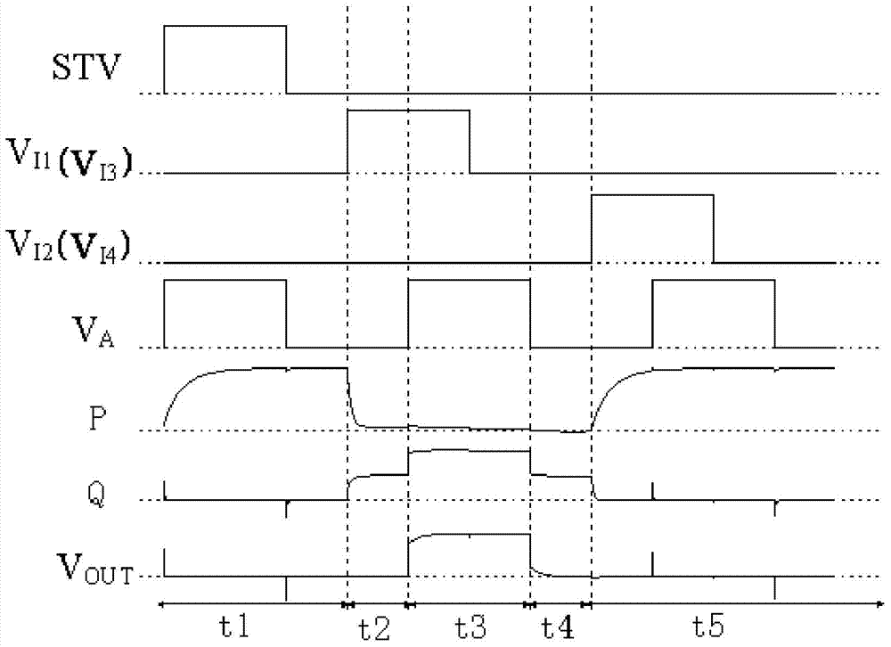
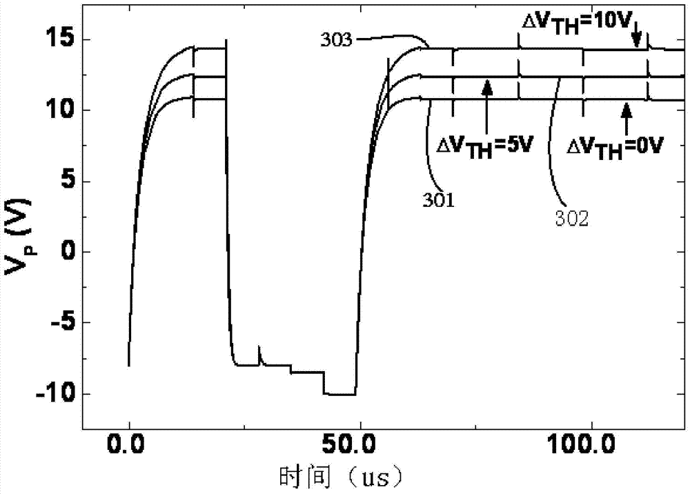
[0068] In the gate driving unit circuit provided in Embodiment 1, the gate driving unit circuit works in the low-level maintenance phase most of the time, and in the low-level maintenance phase, the fifth transistor T5, the sixth transistor T6, the seventh transistor T7, The eighth transistor T8, the ninth transistor T9, and the tenth transistor T10 are in the off state, and the voltage on the second node P needs to ensure that the eleventh transistor T11 and the twelfth transistor T12 are in the on state, so as to connect the first node Q and Signal output terminal V OUT pulled down to the first low level V SS ; Because the fifth transistor T5, the sixth transistor T6, the seventh transistor T7, the eighth transistor T8, the ninth transistor T9, and the tenth transistor T10 have leakage currents passing through, the voltage of the second node P will drop slowly, thereby causing the tenth The conduction capability of the first transistor T11 and the twelfth transistor T12 dec...
Embodiment 3
[0081] Please refer to Figure 7 , based on the gate drive unit circuit provided in Embodiment 1, this embodiment accordingly provides a gate drive circuit, including N cascaded gate drive unit circuits, where N is a positive integer greater than or equal to 4, and the gate The driving unit circuit is the gate driving unit circuit provided in the first embodiment.
[0082] The gate drive circuit also includes a first clock line CK1, a second clock line CK2, a third clock line CK3, a fourth clock line CK4, a first pulse signal line V 1 , the second pulse signal line V 2 , the third pulse signal line V 3 , the fourth pulse signal line V 4 , the initial set signal line ST and the first low-level signal line V S ; The high level arrival time of the clock signal output by the second clock line CK2 lags behind the high level arrival time T / 4 of the clock signal output by the first clock line CK1, and the high level of the clock signal output by the third clock line CK3 The arri...
PUM
 Abstract
Description
Claims
Application Information
 - R&D
- Intellectual Property
- Life Sciences
- Materials
- Tech Scout
- Unparalleled Data Quality
- Higher Quality Content
- 60% Fewer Hallucinations
Browse by: Latest US Patents, China's latest patents, Technical Efficacy Thesaurus, Application Domain, Technology Topic, Popular Technical Reports.
© 2025 PatSnap. All rights reserved.Legal|Privacy policy|Modern Slavery Act Transparency Statement|Sitemap|About US| Contact US: help@patsnap.com


