Running-in device of hydraulic operating mechanism used for high-pressure SF6 breaker

A technology of hydraulic operation and circuit breaker, applied in the direction of protection switch operation/release mechanism, high voltage/high current switch, circuit, etc., can solve the problem of inaccurate simulation of opening and closing load changes, and insufficient influence ability of exhaust hole damping changes , Inability to quickly adjust the opening and closing load, etc., to achieve the effect of fast implementation, shortening the installation and testing time, and improving the efficiency and quality of the factory

Active Publication Date: 2015-06-24
SHENZHEN POWER SUPPLY BUREAU
View PDF5 Cites 3 Cited by
  • Summary
  • Abstract
  • Description
  • Claims
  • Application Information

AI Technical Summary

Problems solved by technology

[0006] The inventors have found that both of the above two running-in methods have deficiencies. The disadvantages are: in the first running-in method, this method is not adaptable, not only cannot accurately simulate the opening and closing load of the high-voltage SF6 circuit breaker In the second running-in mode, whe

Method used


Image

  • Running-in device of hydraulic operating mechanism used for high-pressure SF6 breaker
  • Running-in device of hydraulic operating mechanism used for high-pressure SF6 breaker
  • Running-in device of hydraulic operating mechanism used for high-pressure SF6 breaker

Examples


Example Embodiment

[0041] In order to make the objectives, technical solutions and advantages of the present invention clearer, the present invention will be further described in detail below with reference to the accompanying drawings and embodiments. It should be understood that the specific embodiments described herein are only used to explain the present invention, but not to limit the present invention.

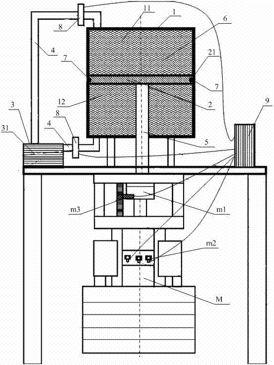
[0042] like figure 1 As shown, in the embodiment of the present invention, a kind of running-in device for the hydraulic operating mechanism on the high-voltage SF6 circuit breaker proposed, which cooperates with the hydraulic operating mechanism M on the high-voltage SF6 circuit breaker, including:

[0043] Fully enclosed cylindrical box 1;

[0044] The piston 2 embedded in the box body 1, the outer surface 21 of the piston 2 abuts against the inner wall of the box body 1, and separates the box body 1 into an upper cavity 11 and a lower cavity 12 that are not connected to each other;

[0...


PUM


Abstract

The embodiment of the invention discloses a running-in device of a hydraulic operating mechanism used for a high-pressure SF6 breaker. The running-in device of the hydraulic operating mechanism used for the high-pressure SF6 breaker comprises a totally enclosed columnar box body, a piston, medium containing device, a driving connecting rod and damping mediums. The piston is embedded inside the box body, the outer surface of the piston is abutted against the inner wall of the box body, and the box body is divided into an upper cavity and a lower cavity by the piston, wherein the upper cavity and the lower cavity are not communicated with each other. The medium containing device is arranged outside the box body, the medium containing device is connected with the upper cavity and the lower cavity through two guide pipes, and the communication is achieved. One end of the driving connecting rod is placed inside the lower cavity and fixed on the piston, and the other end of the driving connecting rod is placed outside the box body and is matched with the hydraulic operating mechanism. The upper cavity and the lower cavity are filled with the damping mediums. When the driving connecting rod moves, the piston is driven to slide along the inner wall of the box body in the direction of facing or deviating from the lower cavity. According to the running-in device of the hydraulic operating mechanism used for the high-pressure SF6 breaker, the adaptability is high, aiming at the damping changing condition of various high-pressure SF6 breakers in the divide-shut braking process, the real-time dynamic closed-loop adjustment on the damping is achieved, the installing and fitting testing time of the hydraulic operating mechanism and the high-pressure SF6 breaker is shortened, and the delivering efficiency and the quality of the mechanism are improved.

Description

technical field [0001] The invention relates to the technical field of high-voltage circuit breakers, in particular to a running-in device for a hydraulic operating mechanism on a high-voltage SF6 circuit breaker. Background technique [0002] The high-voltage SF6 (sulfur hexafluoride) circuit breaker is the most important control element in the high-voltage power transmission system. The operating mechanism provides the driving force for the opening and closing of the high-voltage SF6 circuit breaker. According to the different voltage levels of the high-voltage SF6 circuit breaker. , the operating work required to drive the high-voltage SF6 circuit breaker is also different. [0003] The operating mechanism on the high-voltage SF6 circuit breaker includes a spring operating mechanism and a hydraulic operating mechanism; among them, the spring operating mechanism uses the spring as the energy storage unit, and the mechanical rod is the energy transmission medium to drive th...

Claims


Application Information

Patent Timeline
IPC IPC(8): H01H71/10
CPCH01H11/0062H01H33/34
Inventor 黄荣辉赵奔张欣武星姚森敬刘顺桂赵宇明向真
Owner SHENZHEN POWER SUPPLY BUREAU
Why Eureka
Try Eureka