Axial opposite magnet rare earth permanent magnet generator

A rare earth permanent magnet and generator technology, applied in electromechanical devices, electrical components, electric components, etc., can solve the problems of large generator set, low utilization rate of iron core, inconvenient offline, etc., to improve the utilization rate of windings, The effect of reducing magnetic circuit loss and improving installation efficiency

Inactive Publication Date: 2015-06-24
ARCHITECTURAL ENG INST GENERAL LOGISTICS DEPT P L A +1
View PDF5 Cites 1 Cited by
  • Summary
  • Abstract
  • Description
  • Claims
  • Application Information

AI Technical Summary

Problems solved by technology

[0002] Traditional generators above 10kW used to work through the combined connection of engine-coupling-generator. The utilization rate of traditional generator iron core is low, the consumption is large, and it is inconvenient to go offline
In order to ensure the concentricity between the engine crankshaft and the generator shaft, it needs to be driven through a coupling during installation, which makes the generator set bulky

Method used


Image

  • Axial opposite magnet rare earth permanent magnet generator
  • Axial opposite magnet rare earth permanent magnet generator
  • Axial opposite magnet rare earth permanent magnet generator

Examples


Embodiment Construction

[0028] Below in conjunction with accompanying drawing, the present invention is described in further detail:

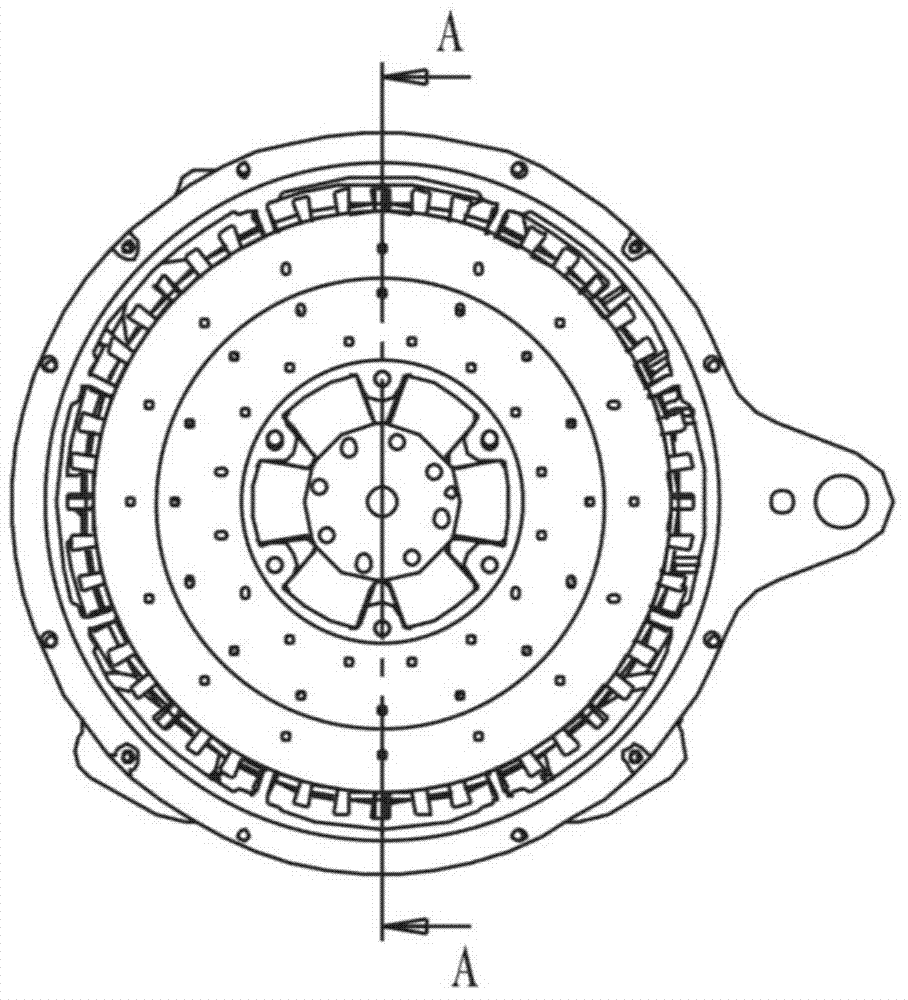
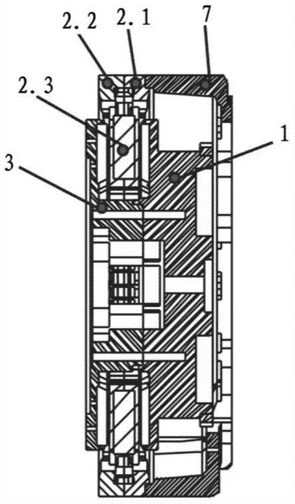
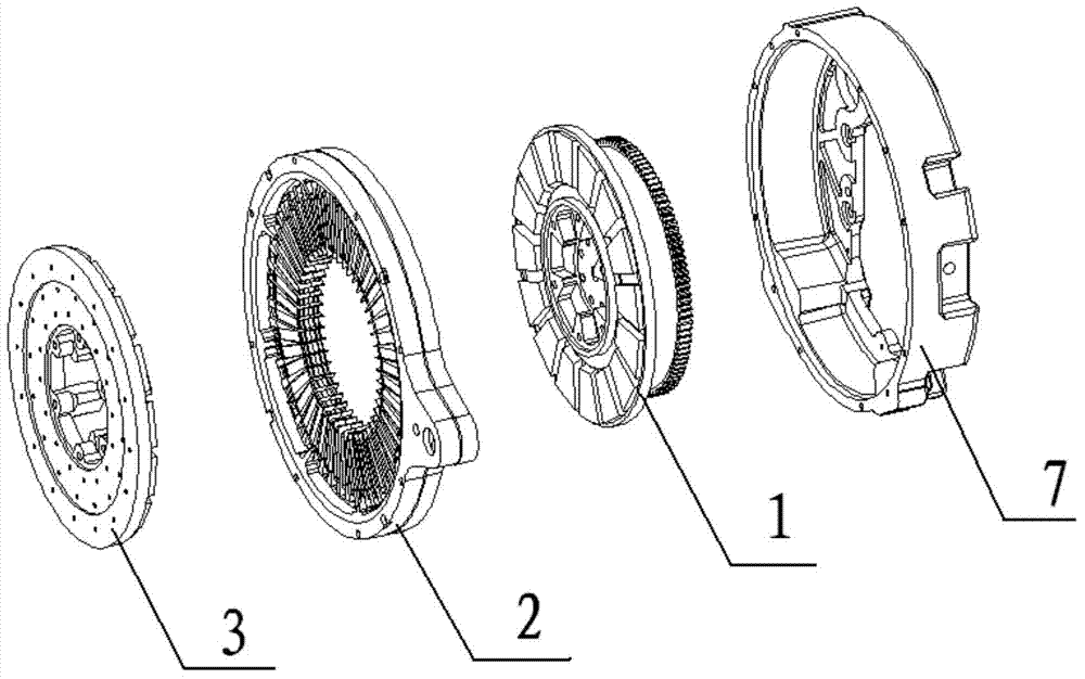
[0029] See Figure 1 and figure 2 As shown, the present invention includes a stator 2.3, a front rotor 1 and a rear rotor 3 at the front and rear ends of the stator 2.3, and a flywheel shell 7 connected with the front rotor 1. The iron core and windings provided in the stator 2.3 are clamped by the chuck front and rear. The positioning is locked with the flywheel housing 7 by bolts. The front rotor 1 and the rear rotor 3 are provided with magnetic steel on the inner circumferential surface of the magnetic yoke, and the two magnetic steels are opposite to each other with the same poles. The rotor is composed of a magnetic tray and a magnetic steel. The magnetic steel is conical and evenly distributed. The distance between the magnetic steel end face and the iron core end face is 2 to 2.5 times. Reduce friction, and at the same time, the connecting section also acts as...


PUM


Abstract

The invention discloses an axial opposite magnet rare earth permanent magnet generator. The generator is composed of a stator, rotors and a shell. The stator is composed of an iron core, clamping pieces, a winding and clamping discs. Compared with a traditional motor, the iron core consumes a small quantity of materials, is convenient to machine and saves energy in the machining process, the utilization rate of the iron core reaches 100%, the winding consumes a small quantity of materials and is easy to machine, and the clamping pieces and the clamping discs are common machined parts. Each rotor is composed of a magnetic tray and magnetic steel. Through the design, the magnetic trays to which the magnetic steel can be attached also play the flywheel and fan roles, and therefore the weight and size of a generator set can be reduced. Compared with a traditional generator, the generator has the advantages of being small in size, light in weight, high in material utilization rate, high in efficiency and the like.

Description

technical field [0001] The invention belongs to the technical field of generators, and relates to a permanent magnet generator, in particular to an axially opposite magnetic rare earth permanent magnet generator. Background technique [0002] Traditional generators above 10kW used to work through the combination of engine-coupling-generator connection. The utilization rate of traditional generator iron cores is low, the consumption is large, and it is inconvenient to go offline. In order to ensure the concentricity between the crankshaft of the engine and the shaft of the generator, it needs to be driven through a coupling during installation, which makes the generator set bulky. SUMMARY OF THE INVENTION [0003] The purpose of the present invention is to solve the above problems and provide an axially aligned rare earth permanent magnet generator. The stator is locked by front and rear chucks and then fixed to the flywheel housing. The front and rear rotors are used as ...

Claims


Application Information

Patent Timeline
Patent Type & Authority Applications(China)
IPC IPC(8): H02K16/02H02K7/02H02K7/18H02K9/04H02K3/28
CPCY02E60/16
Inventor 曹世宏郭万里万永峰胡国昌张福才宁涛沈承
Owner ARCHITECTURAL ENG INST GENERAL LOGISTICS DEPT P L A
Why Eureka
Try Eureka