
Water diffuser branch

A technology for water guns and barrels, which is applied to valves, devices for absorbing fluid energy, valve details, cocks including cutting devices, etc., which can solve problems such as wasting water sources, affecting the service life of water guns, and difficult to ensure the sealing of water guns.

Inactive Publication Date: 2015-07-01
芜湖神途工业装备有限公司
View PDF7 Cites 3 Cited by
  • Summary
  • Abstract
  • Description
  • Claims
  • Application Information

AI Technical Summary

Problems solved by technology

[0002] Existing normal-pressure fire-fighting nozzles can generally only spray a single water column or dovetail-shaped water flow. This traditional fire-fighting nozzle not only wastes a lot of water, but also has poor fire-fighting effects. , under the action of gravity, it is easy to fall to the ground and cannot play the role of fire extinguishing, which greatly reduces the utilization rate of water
Furthermore, a large amount of lost water may also cause secondary water pollution
[0003] In addition, although the existing high-pressure water guns can spray water mist with a small diameter, excessive water pressure will often cause great damage to the valve body of the water gun, making it difficult to ensure the sealing of the water gun, thereby affecting the airtightness of the water gun. The service life of the water gun

Method used


Image

  • Water diffuser branch
  • Water diffuser branch
  • Water diffuser branch

Examples


Embodiment Construction

[0051] Specific embodiments of the present invention will be described in detail below in conjunction with the accompanying drawings. It should be understood that the specific embodiments described here are only used to illustrate and explain the present invention, and are not intended to limit the present invention.

[0052] In the present invention, in the absence of a contrary statement, the orientation words included in the term, such as "inner, outer and lower", only represent the orientation of the term in the normal use state, or the common name understood by those skilled in the art. , and should not be construed as a limitation of this term.

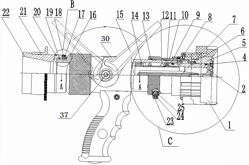
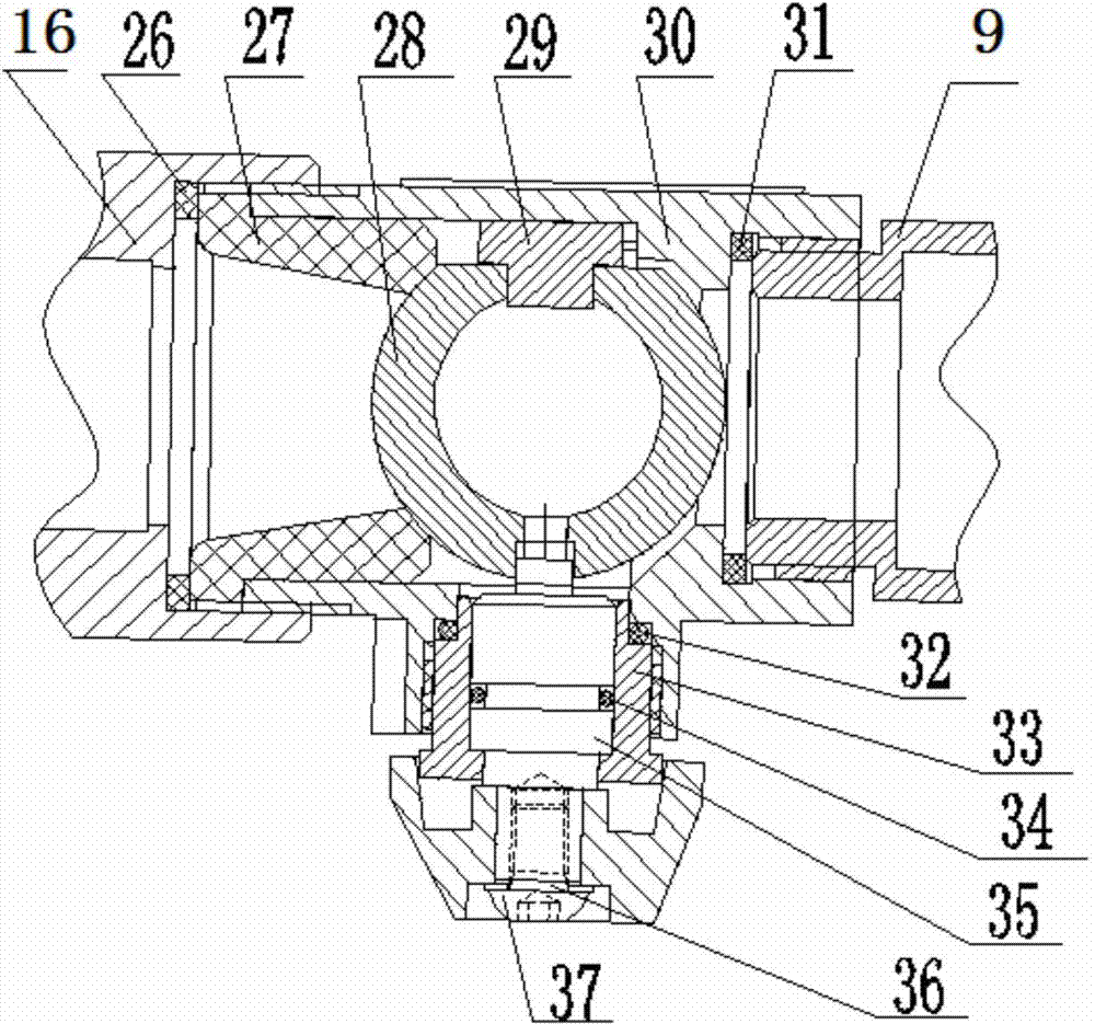
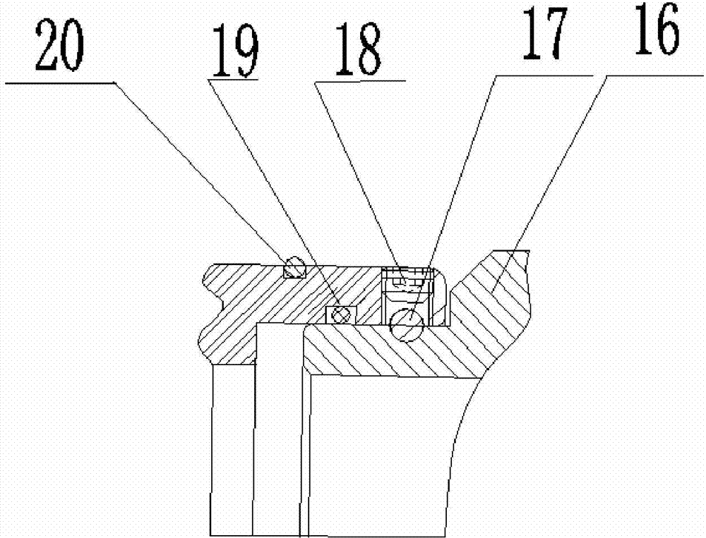
[0053] A kind of direct current spray water gun provided by the present invention, this direct current spray water gun is as figure 1 with figure 2 As shown, it includes a water inlet, a valve body 30 and a water outlet connected in sequence; a valve chamber is formed in the valve body 30, a ball valve sealing seat 27 is prov...


PUM


Abstract

The invention discloses a water diffuser branch comprising a water inlet part, a valve body (30) and a water outlet part, which are sequentially connected with one another, wherein a valve cavity is formed in the valve body; a ball valve sealing seat (27) is arranged at a water inlet end of the valve cavity; a fixed guide block (29) which extends towards the center of the valve cavity is arranged in the valve cavity; a switch handle (15) is fixedly arranged on the outer wall of the valve body; a ball valve (28) is arranged in the valve cavity; one end of the ball valve sinks inwards to form a positioning hole; the end part of the fixed guide block extends into the positioning hole; the other end of the ball valve is connected with a rotating shaft (35); the rotating shaft is connected with the switch handle (15) through the valve body, so that the switch handle is capable of switching on or off the ball valve by driving the rotating shaft; a first sealing ring (26) is arranged at the connected part of the ball valve sealing seat and the water inlet part; and a second sealing ring (31) is arranged at the connected part of the valve body and the water outlet part. The water diffuser branch is capable of bearing high pressure water and is capable of spraying water mist, so that the utilization rate of fire-fighting water is improved.

Description

technical field [0001] The invention relates to a fire fighting device, in particular to a direct current spray water gun. Background technique [0002] Existing normal-pressure fire-fighting nozzles can generally only spray a single water column or dovetail-shaped water flow. This traditional fire-fighting nozzle not only wastes a lot of water, but also has poor fire-fighting effects. , under the action of gravity, it is easy to fall to the ground and cannot play the role of fire extinguishing, which greatly reduces the utilization rate of water. Further, a large amount of lost water may also cause secondary water pollution. [0003] In addition, although the existing high-pressure water guns can spray water mist with a small diameter, excessive water pressure will often cause great damage to the valve body of the water gun, making it difficult to ensure the sealing of the water gun, thereby affecting the airtightness of the water gun. The service life of the water gun. ...

Claims


Application Information

Patent Timeline
IPC IPC(8): A62C17/00A62C31/00F16K5/08F16K5/06
CPCA62C17/00A62C31/02A62C31/28F16K5/06F16K47/023
Inventor 赵秀龙冯学农缪峰云田兆东芮文兵黄建华
Owner 芜湖神途工业装备有限公司
Learn More