Airtight plugging device and method for sampling pipeline

A sampling pipeline and air-sealing technology, which is applied in the direction of measuring devices, fluid tightness testing, pipe components, etc., can solve the problems of shortened pipeline length, time-consuming and labor-intensive, low safety, etc., and achieve high safety, Easy to operate, good sealing effect

Pending Publication Date: 2019-03-12
XI AN RAILWAY TRANSPORTATION EQUIP
View PDF0 Cites 1 Cited by
  • Summary
  • Abstract
  • Description
  • Claims
  • Application Information

AI Technical Summary

Problems solved by technology

[0004] Aiming at the defects and deficiencies in the prior art, the present invention provides a sampling pipeline gas sealing device and method, which overcomes the tim

Method used


Image

  • Airtight plugging device and method for sampling pipeline
  • Airtight plugging device and method for sampling pipeline
  • Airtight plugging device and method for sampling pipeline

Examples


Embodiment 1

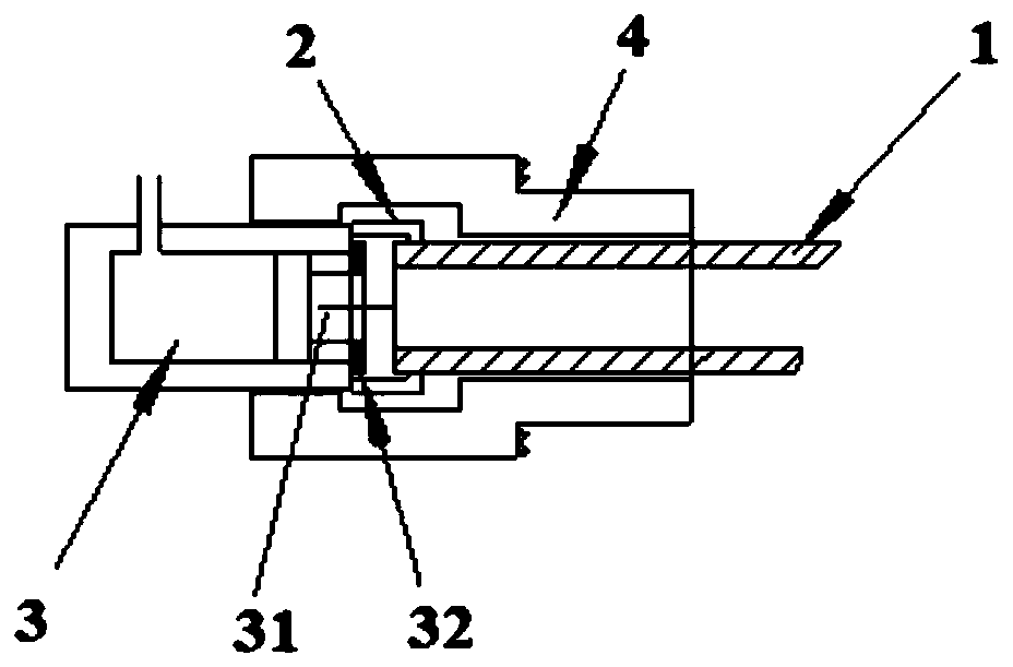
[0033] like Figure 3 to Figure 4 As shown, the present embodiment provides a sampling pipeline air-tight sealing device, which is used to seal the nozzle of the sampling pipeline 1, including a ferrule 2, an oil cylinder 3 and a drill chuck 4; one end of the ferrule 2 Connect the oil cylinder 3, the other end is set on the nozzle of the sampling pipeline 1, one end of the drill chuck 4 is sleeved on the outer wall of the oil cylinder 3, and the other end of the drill chuck 4 is used to fasten the sample near the nozzle of the sampling pipeline 1 On the outer wall of the pipeline 1; the ferrule 2, the oil cylinder 3 and the drill chuck 4 are coaxially arranged, and the drill chuck 4 can lock the oil cylinder 3, the ferrule 2 and the sampling pipeline 1. The ferrule 2 in this embodiment , each parts of oil cylinder 3 and drill chuck 4 are conventional parts. Through the above-mentioned technical scheme, the present invention is easy to operate and high in efficiency; the oil c...

Embodiment 2

[0038] This embodiment provides a method for air-tight sealing of the sampling pipeline. The method adopts a sampling pipeline air-sealing device to air-tightly seal the sampling pipeline, and specifically includes the following steps:

[0039] Step 1: Put the drill chuck on the outer wall of the sampling pipeline;

[0040] Step 2: Put one end of the through hole of the ferrule on the oil cylinder, and position the ferrule axially through the annular limit protrusion, and the other end of the ferrule is set on the outer wall of the sampling pipe mouth and screw clamped;

[0041] Step 3: Then move the drill chuck axially to the outside of the oil cylinder, ferrule and sampling pipe mouth; tighten the thread pairs at both ends of the drill chuck respectively, so that one end of the drill chuck clamps the oil cylinder, and the other end clamps the sample pipeline nozzle;

[0042] Step 4: pressurize the oil cylinder, and the piston rod drives the sealing gasket to extend until th...


PUM


Abstract

The invention discloses an airtight plugging device and method for a sampling pipeline. The device is used for plugging a pipe orifice of the sampling pipeline and comprises a cutting sleeve, an oil cylinder and a drill chuck, wherein one end of the cutting sleeve is connected with the oil cylinder, and the other end of the cutting sleeve is used for being arranged on the pipe orifice of the sampling pipeline in a sealing and sleeving mode; one end of the drill chuck is arranged on the outer wall of the oil cylinder in the sealing and sleeving mode, and the other end of the drill chuck is usedfor being fastened on the outer wall of the sampling pipeline close to the pipe orifice of the sampling pipeline in the sealing mode; the cutting sleeve, the oil cylinder and the drill chuck are coaxially arranged; and the drill chuck can lock the oil cylinder, the cutting sleeve and the sampling pipeline. The airtight plugging device and method have the advantages of easiness in operation and high efficiency. The oil cylinder is strong in compression force and good in sealing effect. The tested pipe orifice cannot be damaged, and nondestructive testing is realized. The drill chuck forms a double-safety mechanism, therefore the device cannot fly out to hurt people during testing, and the safety is high.

Description

technical field [0001] The invention specifically relates to a sampling pipeline air sealing device and method. Background technique [0002] The sampling pipeline is the pipeline for extracting the liquid sample in the container on a certain type of military vehicle. The airtightness test of the pipeline must be carried out before loading to verify that its quality is qualified and there is no leakage. Before the airtightness test, the sampling pipeline must be checked The mouth should be blocked, otherwise the test cannot be carried out. Since the samples taken are all for the purpose of chemical testing, the diameters of common sampling pipes are small, such as Φ6, Φ8, Φ12 and other specifications. Most of the materials are stainless steel and aluminum alloy. There are straight pipes, bent pipes, with joints, without joints, etc. in the structure. like figure 1 (a) The sampling pipeline shown in (a) is different according to the product and the medium installed, and g...

Claims


Application Information

Patent Timeline
IPC IPC(8): F16L55/10G01M3/02
CPCF16L55/10G01M3/022
Inventor 辛辉张彤阳麻彬彬
Owner XI AN RAILWAY TRANSPORTATION EQUIP
Why Eureka
Try Eureka