Clamp for friction stir welding

A technology of friction stir welding and fixtures, which is applied in the direction of manufacturing tools, welding equipment, welding equipment, etc., can solve the problems of non-reverse deformation of fixtures, affect welding quality, and insufficient clamping force of fixtures, so as to reduce manual operations and improve welding quality , The effect of improving welding efficiency

Pending Publication Date: 2019-09-03
JIANGSU BEIREN ROBOT SYST CO LTD
View PDF7 Cites 8 Cited by
  • Summary
  • Abstract
  • Description
  • Claims
  • Application Information

AI Technical Summary

Problems solved by technology

The traditional friction stir welding fixture has the following disadvantages: 1) If the dimensions of the plates to be welded are relatively similar, the traditional fixture lacks a reasonable and correct error-proof structure; 2) The clamping force of the traditional fixture is not enough, and the stirring The downforce of the stirring needle in friction welding is only 1T. Under such a large pressure, the gap between the plates will change due to deformation and other reasons during the welding process, which will affect the welding quality; 3) The traditional fixture has no The anti-deformation function makes the quality of welding products unable to meet customer requirements, etc.

Method used


Image

  • Clamp for friction stir welding
  • Clamp for friction stir welding
  • Clamp for friction stir welding

Examples


Embodiment Construction

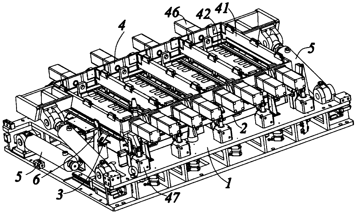
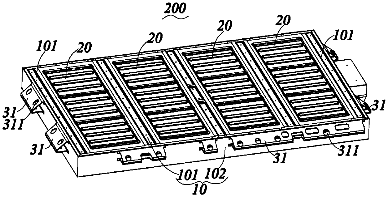
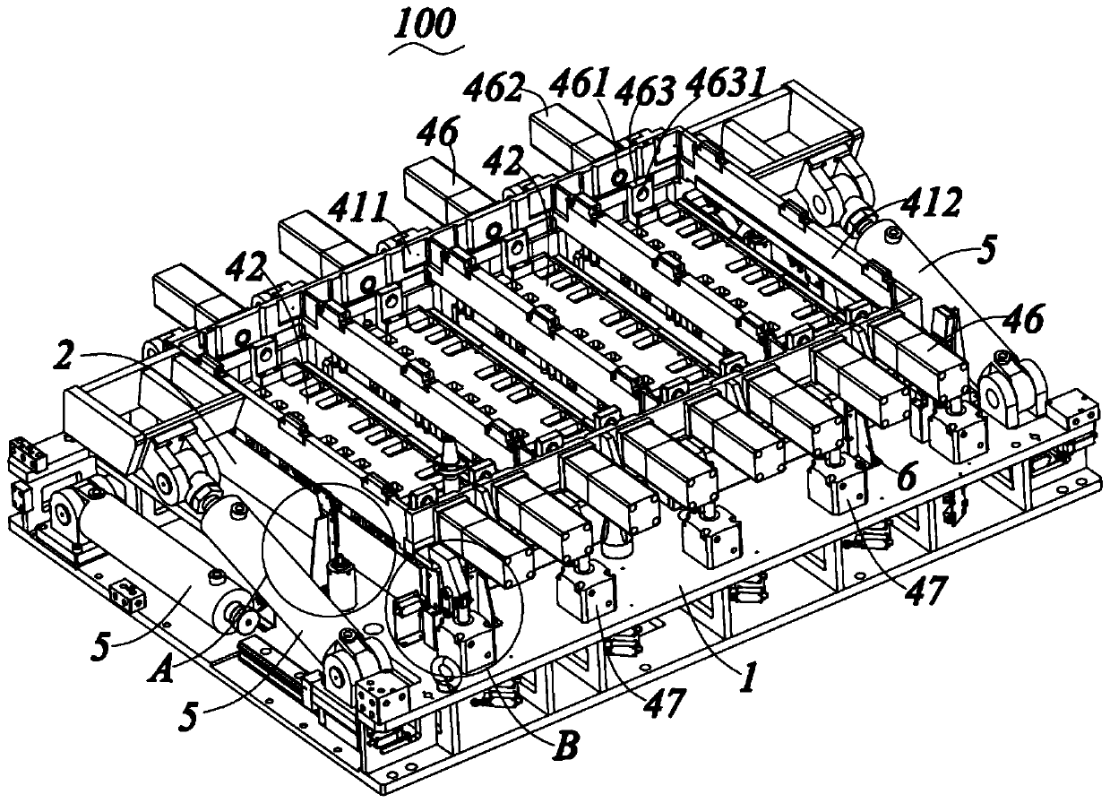
[0026] The present invention will be described in detail below in conjunction with various embodiments shown in the accompanying drawings, please refer to Figure 1 to Figure 8 Shown is a preferred embodiment of the present invention. However, it should be noted that these embodiments do not limit the present invention, and any functional, method, or structural equivalent transformations or substitutions made by those skilled in the art based on these embodiments fall within the protection scope of the present invention.

[0027] In the description of the present invention, it should be understood that the orientation or positional relationship indicated by the terms "upper", "lower", "height", etc. is based on the orientation or position of the clamp for friction stir welding in normal use The relationship is only for the convenience of describing the present invention and simplifying the description, but does not indicate or imply that the referred device or element must hav...


PUM


Abstract

The invention provides a clamp for friction stir welding. The clamp is used for clamping a frame and aluminum plates to be welded, wherein the frame comprises a plurality of cross beams which are arranged in parallel and are arranged at intervals and longitudinal beams connecting the end parts of the plurality of cross beams in sequence; the clamp used for friction stirring welding comprises a base, a positioning structure, a pressing mechanism, a turnover driving mechanism, wherein a supporting frame is arranged on the base and is used for supporting the frames and the aluminum plates; the positioning structure is arranged between the base and the frames so as to locate the frames; the pressing mechanism is rotationally connected to the base to press the frames and the aluminum plates; and the turnover driving mechanism is fixed on the base and is used for driving the pressing mechanism to turn over. The frames are accurately positioned, it is guaranteed that the frames and the aluminum plates are completely positioned, and the influence of welding quality caused by positioning problems is avoided; and meanwhile, the manual operation is reduced, the welding efficiency is improved,the pressing mechanism can provide enough press force, so that gaps between the frames and the aluminum plates are prevented from changing during a welding process, and the welding quality is furtherimproved.

Description

technical field [0001] The invention relates to the field of welding, in particular to a fixture for friction stir welding. Background technique [0002] Friction stir welding refers to the use of high-speed rotating stirring needle and the friction between the welded workpiece to generate heat to locally plasticize the welded workpiece. When the stirring needle moves forward along the workpiece, the plasticized material acts on the rotational friction of the stirring needle. It flows from the front of the stirring needle to the rear, and forms a dense friction stir welding seam under the extrusion of the stirring needle. [0003] Friction stir welding does not require high equipment, but the rigidity of welding equipment and fixtures is extremely important. The traditional friction stir welding fixture has the following disadvantages: 1) If the dimensions of the plates to be welded are relatively similar, the traditional fixture lacks a reasonable and correct error-proof s...

Claims


Application Information

Patent Timeline
Patent Type & Authority Applications(China)
IPC IPC(8): B23K20/12B23K37/04
CPCB23K20/126B23K37/0443
Inventor 蔡小认郭敬马宏波林涛朱振友
Owner JIANGSU BEIREN ROBOT SYST CO LTD
Why Eureka
Try Eureka