Pneumatic wheel brake for a vehicle

A wheel brake, vehicle technology, applied in the direction of brakes, brake types, drum brakes, etc., to achieve the effect of avoiding power consumption

Active Publication Date: 2013-03-06
ZF CV SYST EURO BV
View PDF7 Cites 8 Cited by
  • Summary
  • Abstract
  • Description
  • Claims
  • Application Information

AI Technical Summary

Problems solved by technology

However, such compensatory adjustments by manipulating electrical hold-downs may be undesirable, for example when power is to be saved

Method used


Image

  • Pneumatic wheel brake for a vehicle
  • Pneumatic wheel brake for a vehicle
  • Pneumatic wheel brake for a vehicle

Examples


Embodiment Construction

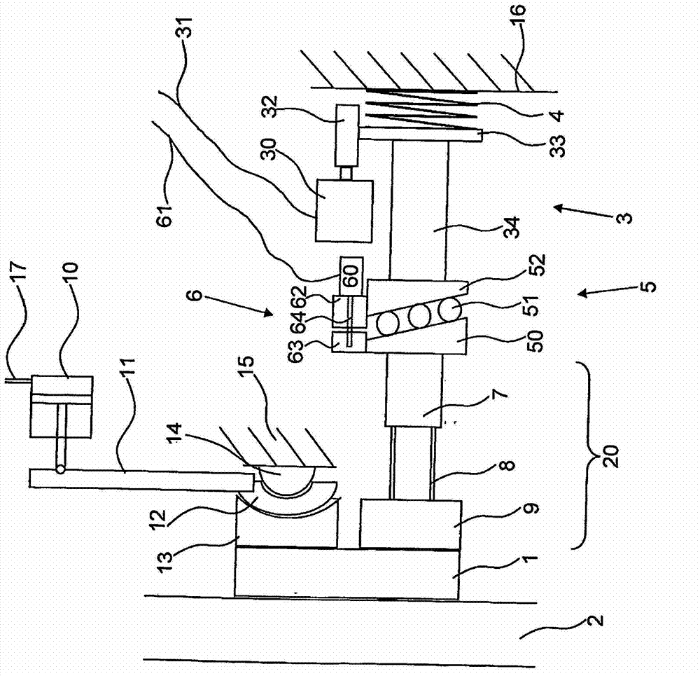
[0036] figure 1 A pneumatic wheel brake for a vehicle is shown in a very schematic diagram form. A compressed air cylinder 10 and a pressing device 20 connected to the compressed air cylinder 10 and capable of being manipulated by the compressed air cylinder 10 are shown. The hold-down device 20 has a brake lever 11, which has an operating element 12 provided with an operating contour at its end opposite to the point of action of the compressed air cylinder 10, which can be used for example with an eccentric or camshaft Form to construct. The actuating element 12 acts on a first pressure piece 13 configured with a corresponding relative profile, which pressure piece finally acts on the first brake element in the form of the brake lining 1. The actuating element 12 is supported rearward via a support element 14 on a component fixed to the housing of the wheel brake (for example, the brake cover 15).

[0037] By the manipulation of the compressed air cylinder 10 caused by filling...


PUM


Abstract

The invention relates to a pneumatic wheel brake for a vehicle, wherein the wheel brake has at least one brake lever (11) that can be operated by a compressed air cylinder (10) and a brake application device (20) that can be operated by the brake lever (11), wherein by means of said brake application device a first brake element (1) can be pressed against a second brake element (2) when the brake lever (11) is operated, and the wheel brake has an actuating device (3) that can be driven by an electric motor, wherein by means of said actuating device force can be applied to at least parts (7, 8, 9) of the brake application device (20), at least when the brake lever (11) is not operated, and thereby the first brake element (1) can be pressed against the second brake element (2). Furthermore, the wheel brake has a spring accumulator element (4), which is arranged outside the compressed air cylinder (10), wherein force can be applied to the spring accumulator element (4) by the actuating device (3) that can be driven by an electric motor and force can be applied to at least parts (7, 8, 9) of the brake application device (20) by the spring accumulator element, at least when the brake lever (11) is not operated, and thereby the first brake element (1) can be pressed against the second brake element (2).

Description

Technical field [0001] The invention relates to a pneumatic wheel brake for a vehicle according to the preamble of patent claim 1. Background technique [0002] This kind of pneumatic wheel brake is known from EP 1384913B1. It is suggested here that the second expansion device is provided in addition to the first expansion device. The second expansion device is part of the electrically operated compression device [U1]. In this way, it is possible to realize the parking brake function with less installation space, especially because it is not necessary to use a longer combination cylinder as a pneumatic control cylinder, but a simpler and shorter brake cylinder. . [0003] In the case of the principle of the electrically controllable parking function known from EP 1384913B1, after the parking brake has been inserted (that is to say after stopping the vehicle), especially in the case of a heated brake, the following requirements may exist, That is, the reduction of the braking fo...

Claims


Application Information

Patent Timeline
Patent Type & Authority Applications(China)
IPC IPC(8): F16D65/14F16D55/226F16D51/00F16D65/18
CPCF16D2125/36F16D65/18F16D2123/00F16D2121/02F16D2121/24B60T1/06F16D65/16F16D2125/582F16D55/226F16D51/00F16D2121/08
Inventor 彼得·拜尔奥拉夫·扬茨
Owner ZF CV SYST EURO BV
Why Eureka
Try Eureka