Turning cutter wear state monitoring system

A wear state and monitoring system technology, applied in turning equipment, manufacturing tools, accessories of toolholders, etc., can solve the problems of imperfect wear monitoring, insensitive signal characteristics, and expensive monitoring costs.

Inactive Publication Date: 2015-07-01
XUZHOU NORMAL UNIVERSITY
View PDF9 Cites 40 Cited by
  • Summary
  • Abstract
  • Description
  • Claims
  • Application Information

AI Technical Summary

Problems solved by technology

[0004] Purpose of the invention: In order to overcome the deficiencies in the prior art, the present invention provides a monitoring system for the wear state of turning tools, which is used to solve the pr

Method used


Image

  • Turning cutter wear state monitoring system
  • Turning cutter wear state monitoring system
  • Turning cutter wear state monitoring system

Examples


Embodiment Construction

[0035] The present invention will be further described below in conjunction with the accompanying drawings.

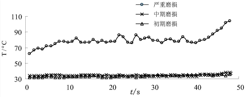
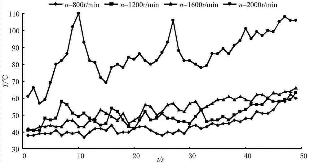
[0036] Select turning tools under three different wear states: initial wear, mid-term wear, and severe wear, and conduct turning tests for each tool according to the scheme shown in Table 1, and conduct 12 tests for each given turning depth e , the tool in each state can be turned 36 times, and the time of each test is set to 1 minute.

[0037] Table 1

[0038]

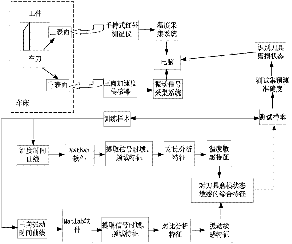
[0039] Such as figure 1 Said, build the turning tool wear state monitoring system of the present invention, comprise signal acquisition system and identification tool wear state system;

[0040] The signal acquisition system includes a temperature acquisition system and a vibration signal acquisition system. The temperature acquisition system collects the temperature at the rake face of the tool through the OS523E-2 infrared thermometer produced by the U.S. OMEGA company. The vibration signal acquisition ...


PUM


Abstract

The invention discloses a turning cutter wear state monitoring system. The turning cutter wear state monitoring system comprises a signal collecting system and a cutter wear state identifying system; the signal collecting system comprises a temperature collecting system and a vibration signal collecting system, wherein the temperature collecting system collects temperature of a cutter point of a rake face of the cutter, and the vibration signal collecting system collects a three-dimensional vibrating signal at the lower surface of a cutter handle corresponding to the utter point of the rake face of the cutter; after pretreating the signal collected by the signal collecting system, the sensitive characteristic of the cutter wear state is obtained and transmitted to the well-trained cutter wear state identifying system; thus the wear state of the cutter is judged through the cutter wear state identifying system. The turning cutter wear state monitoring system is simple and applicable, and is convenient to operate; moreover, the sensor in use is relatively universal in use, moderate in cost, and easy to build up a testing system; the turning cutter wear state monitoring system can largely reduce the monitoring cost, effectively identify the wear state of the cutter and reduce the cutter waste.

Description

technical field [0001] The invention relates to the field of machining, in particular to a monitoring system for the wear state of machining tools. Background technique [0002] Tool wear is a common phenomenon in machining. Tool wear will reduce the machining accuracy of the workpiece, deteriorate the surface roughness of the workpiece, reduce the service life of the equipment, generate turning heat, increase downtime, and directly reduce production efficiency and revenue. In order to avoid losses caused by tool wear, most factories currently replace tools based on processing experience and average tool life. This often results in the tool being worn but not replaced or not severely worn. This method cannot effectively solve the problem. Machining problems caused by tool wear. Therefore, it is very necessary to monitor the wear state of cutting tools, especially with the gradual popularization of modern automatic manufacturing systems, automatic monitoring of cutting tools...

Claims


Application Information

Patent Timeline
IPC IPC(8): B23B25/00B23Q17/09
CPCB23B25/06B23Q17/0957B23Q17/0985
Inventor 李顺才吴明明魏巍袁冠雷杨睿
Owner XUZHOU NORMAL UNIVERSITY
Why Eureka
Try Eureka