
Double-oblique-face double-way floating pairing workpiece automatic clamping jig

An automatic clamping and double-slope technology, which is applied in the direction of manufacturing tools, metal processing machinery parts, clamping, etc., can solve the problems of reducing workpiece processing accuracy, dimensional deterioration, and positioning accuracy reduction, and achieves adjustable clamping force , Simple structure, reliable clamping effect

Active Publication Date: 2015-07-01
DONGFENG MOTOR CORP HUBEI
View PDF5 Cites 14 Cited by
  • Summary
  • Abstract
  • Description
  • Claims
  • Application Information

AI Technical Summary

Problems solved by technology

Affected by the draft angle of the clamping surface of the workpiece, the workpiece usually moves upward during the clamping process, which reduces the positioning accuracy of the workpiece, thus increasing the dimensional variation of the workpiece after processing and reducing the machining accuracy of the workpiece
The vise-like fixture structure can usually only be clamped manually for a single piece, and the clamping force depends on the operator's feel and cannot specify a specific value.
In the process of multiple clamping operations, the labor intensity of the operator is high, which is not suitable for clamping processing of large quantities of parts

Method used


Image

  • Double-oblique-face double-way floating pairing workpiece automatic clamping jig
  • Double-oblique-face double-way floating pairing workpiece automatic clamping jig
  • Double-oblique-face double-way floating pairing workpiece automatic clamping jig

Examples


Embodiment Construction

[0020] The present invention will be further described in detail below in conjunction with the accompanying drawings and specific embodiments to facilitate a clear understanding of the present invention, but they do not limit the present invention.

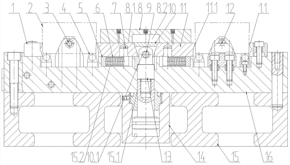
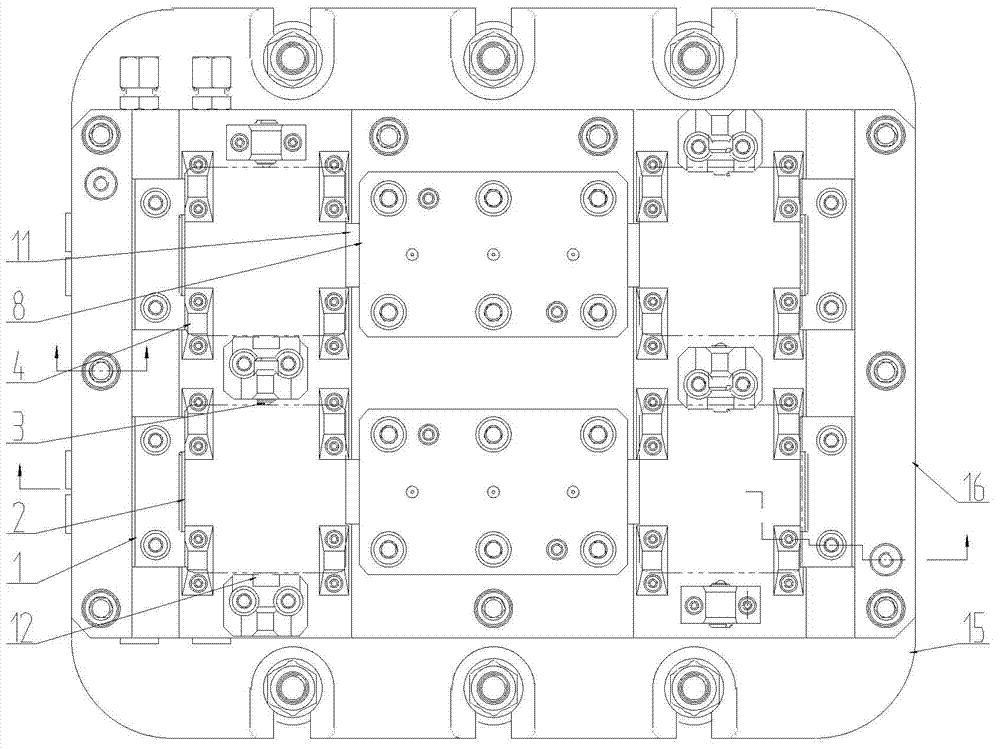
[0021] Such as figure 1 As shown, the present invention includes a cast iron base 15, on which a bottom plate 16 with an oil circuit is installed through an inner hexagon screw and a cylindrical pin, and an oil circuit board type hydraulic cylinder 14 is installed on the bottom plate 16 through an inner hexagon screw, and the oil of the bottom plate 16 The road communicates with the oil circuit of the hydraulic cylinder 14, leading to the rod chamber and the rodless chamber of the hydraulic cylinder 14 respectively.

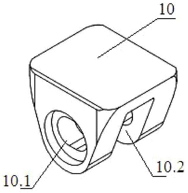
[0022] combine image 3 , Figure 4 As shown, the piston rod of the hydraulic cylinder 14 passes through the through hole 15.1 opened in the bottom plate 16 and is fixedly connected with the bottom of the connectin...


PUM


Abstract

The invention relates to a double-oblique-face double-way floating pairing workpiece automatic clamping jig and relates to a workpiece jig for cutting the upper end face of a workpiece with the appearance contour similar to a rectangle. The jig comprises a base, a bottom plate arranged on the base, an oil pressure cylinder arranged in the base, a double-oblique-face pulling block hinged to a piston rod which extends out of the upper portion of the bottom plate from the oil pressure cylinder, moving oblique face jaws in sliding connection to the bottom plate and a fixed oblique face locating jaw which is fixed on the bottom plate and is used for being matched with the moving oblique face jaws. The number of the moving oblique face jaws is two. The two moving oblique face jaws are arranged on the two sides of the double-oblique-face pulling block symmetrically and respectively and are in contact connection with the two side oblique faces of the double-oblique-face pulling block. The jig can clamp the workpiece in a pairing mode, when the workpiece is clamped, downward component force is applied on the workpiece, and the phenomenon of upwarping of the workpiece with pattern draft during a clamping process is avoided.

Description

technical field [0001] The invention relates to a workpiece fixture for cutting the upper end face of a workpiece with a similar rectangular outline, in particular to a double-slope bidirectional floating paired workpiece automatic clamping fixture. Background technique [0002] In machining, the machining of a workpiece with a draft slope similar to a rectangular shape is usually clamped by a vise or a structure similar to a vise. Affected by the draft angle of the clamping surface of the workpiece, the workpiece usually moves upward during the clamping process, which reduces the positioning accuracy of the workpiece, thus increasing the dimensional variation of the processed workpiece and reducing the machining accuracy of the workpiece. The vise-like fixture structure can usually only be clamped manually for a single piece, and the clamping force depends on the operator's feel and cannot specify a specific value. In the process of multiple clamping operations, the labor ...

Claims


Application Information

Patent Timeline
Patent Type & Authority Applications(China)
IPC IPC(8): B23Q3/08
CPCB23Q3/082
Inventor 刘炼红尤海泉叶丛超成祥李保国武朝峰易淑祥贺绍峰吴汉良
Owner DONGFENG MOTOR CORP HUBEI
Learn More