A screw type dipping equipment

A screw-type, dipping technology, applied in the direction of coating, etc., can solve the problems of damage to the health of operators, short fiber dipping time, insufficient dipping, etc., to achieve the effect of convenient observation, simple equipment, and good dipping effect

Active Publication Date: 2017-11-07
SHANDONG UNIV
View PDF4 Cites 0 Cited by
  • Summary
  • Abstract
  • Description
  • Claims
  • Application Information

AI Technical Summary

Problems solved by technology

Most of the current dipping equipment is in the form of a dipping tank. In a tank, two rollers press the fiber into the glue that needs to be dipped. The distance that the fiber can be dipped is the distance between the two rollers. The distance between the dipping method is short, the dipping time is short, the dipping is not enough, and the effect is not good
Moreover, this kind of dipping is an open type dipping. The glue is poured into the glue tank, and the glue is in contact with the outside atmosphere. Some glue components contain volatile substances, so that the volatile substances will diffuse into the outside air. Not only pollute the environment, but also damage the health of operators

Method used


Image

  • A screw type dipping equipment
  • A screw type dipping equipment
  • A screw type dipping equipment

Examples


Embodiment 1

[0034] Take 0030 bundles of T700-12K carbon fiber dipped in epoxy resin with a viscosity of 3000mps as an example.

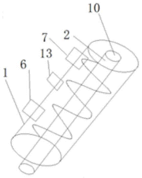
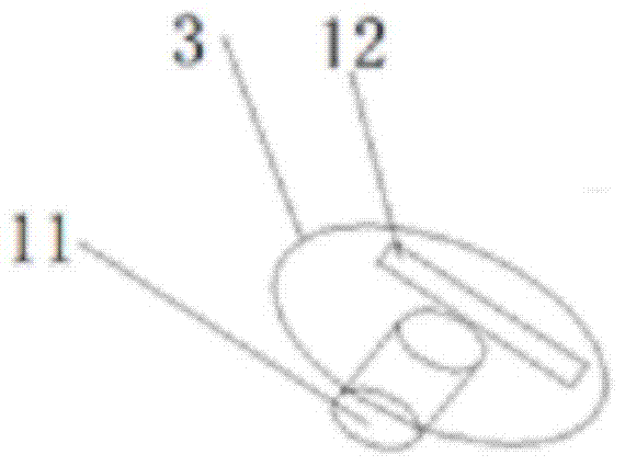
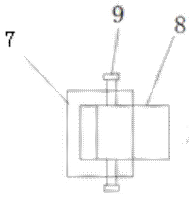
[0035] The dipping sleeve 1 and the dipping shaft 2 are made of 304 stainless steel. Insert 30 bundles of T700-12K carbon fiber through the tow inlet 7, wind them on the dipping shaft 2 according to the thread direction, and pass them out from the tow exit 6 after winding. The thread section of the dipping shaft 2 is trapezoidal, and wrap the Put the dipping shaft 2 of good carbon fiber into the dipping sleeve 1, insert one end of the dipping shaft 1 into the first cylindrical hole 10, align the second cylindrical hole 11 with the other end of the dipping shaft 2, and then cover the dipping sleeve Canister cover 3. Place the installed dipping sleeve 1 on the support 4. The insulation cover 5 is heated by a carbon fiber electric heater, and the insulation temperature is set at 40°C. Pour epoxy resin from the injection port 13. Observe the height of the glue i...

Embodiment 2

[0037] Take 50 bundles of 12K glass fibers dipped in phenolic resin with a viscosity of 7000mps as an example.

[0038] The dipping sleeve 1 and the dipping shaft 2 adopt polytetrafluoroethylene. Put 50 bundles of 12K glass fiber through the tow inlet 7, wind it on the dipping shaft 2 according to the thread direction, and pass it out from the tow outlet 6 after winding. The cross section of the thread is triangular. Put the shaft 2 into the dipping sleeve 1, insert one end of the dipping shaft 2 into the first cylindrical hole 10, align the second cylindrical hole 11 with the other end of the dipping shaft 2, and then cover the dipping sleeve cover 3. Place the installed dipping sleeve 1 on the support 4. The heat preservation cover 5 adopts the water heat preservation of setting temperature through the interior, and the heat preservation temperature is set to 60 ℃. Pour the phenolic resin from the injection port 13. Observe the height of the glue in the dipping sleeve 1 f...


PUM


Abstract

The invention relates to a screw type dipping equipment, comprising a dipping sleeve, a dipping shaft fitted inside the dipping sleeve, a glue injection port, a tow inlet and a tow outlet arranged on the same side of the dipping sleeve , the tow inlet and tow outlet are respectively located at the left and right ends of the dipping sleeve. The dipping shaft is a screw type dipping shaft, and the thread length of the dipping shaft is less than the length of the dipping sleeve. The glue is poured from the glue injection port, and the size of the tow inlet and tow outlet can be adjusted by adjusting the block and fastening bolts. By adjusting the size of the tow inlet to ensure that the tow entering the dipping sleeve is neat Generally, the glue content of the fibers coming out of the dipping sleeve after dipping is controlled by adjusting the size of the tow outlet. The invention is a closed glue dipping device, the glue liquid does not contact with the outside atmosphere, and has no pollution; the screw type glue dipping is adopted, all tows enter the glue liquid, the contact time with the glue liquid is long, the glue dipping is sufficient, and the effect of the glue dipping is good.

Description

technical field [0001] The invention relates to the field of dipping tanks, in particular to a screw type dipping equipment. Background technique [0002] With the development of fiber-reinforced resin-based composite materials, the application of dipping equipment is becoming more and more popular. Most of the current dipping equipment is in the form of a dipping tank. In a tank, two rollers press the fiber into the glue that needs to be dipped. The distance that the fiber can be dipped is the distance between the two rollers. The distance between fibers is short in this dipping method, the dipping time is short, the dipping is not sufficient, and the effect is not good. Moreover, this kind of dipping is an open type dipping. The glue is poured into the glue tank, and the glue is in contact with the outside atmosphere. Some glue components contain volatile substances, so that the volatile substances will diffuse into the outside air. It not only pollutes the environment, ...

Claims


Application Information

Patent Timeline
Patent Type & Authority Patents(China)
IPC IPC(8): B29B15/14
Inventor 朱波乔琨王永伟
Owner SHANDONG UNIV
Why Eureka
Try Eureka