
clipping filter

A filter and filter body technology, which is used in wellbore/well components, earthwork drilling, wellbore flushing, etc., can solve the problems of reducing the work intensity of derrick workers, not placing conventional filter elements, and increasing the work intensity of derrick workers. The effect of meeting the needs of offshore operations, reducing the labor intensity of workers, and reliable performance

Active Publication Date: 2017-03-15
CNOOC ENERGY TECH & SERVICES
View PDF5 Cites 0 Cited by
  • Summary
  • Abstract
  • Description
  • Claims
  • Application Information

AI Technical Summary

Problems solved by technology

[0002] At present, during offshore drilling operations, when the lower part of the drilling tool assembly carries precision instruments for operations (logging operations, directional well operations, etc.), these precision instruments have very high requirements for mud, so special equipment is required to filter the mud; and now Most of the 5-1 / 2" drill pipe fasteners used at sea are HT55 and most of the 5-7 / 8" drill pipe fasteners are XT57. These two fasteners have no space for conventional filter elements; at the same time, with the development of science and technology , most of the drilling platforms now use iron drillers to replace the derrick work in the past. When placing conventional filter elements in the drill pipe column, it is necessary to arrange special personnel to be on duty on the second floor platform, which will inevitably increase the work intensity of the derrick workers. Therefore, it is particularly important to design a general-purpose filter that can filter out harmful solid phases in the mud and ensure the safe and stable operation of downhole precision instruments to meet the needs of offshore operations; it can also reduce the work intensity of derrick workers and reduce unnecessary operating procedures.

Method used


Image

  • clipping filter
  • clipping filter

Examples


Embodiment Construction

[0013] In order to further understand the invention content, characteristics and effects of the present invention, the following examples are given, and detailed descriptions are as follows in conjunction with the accompanying drawings:

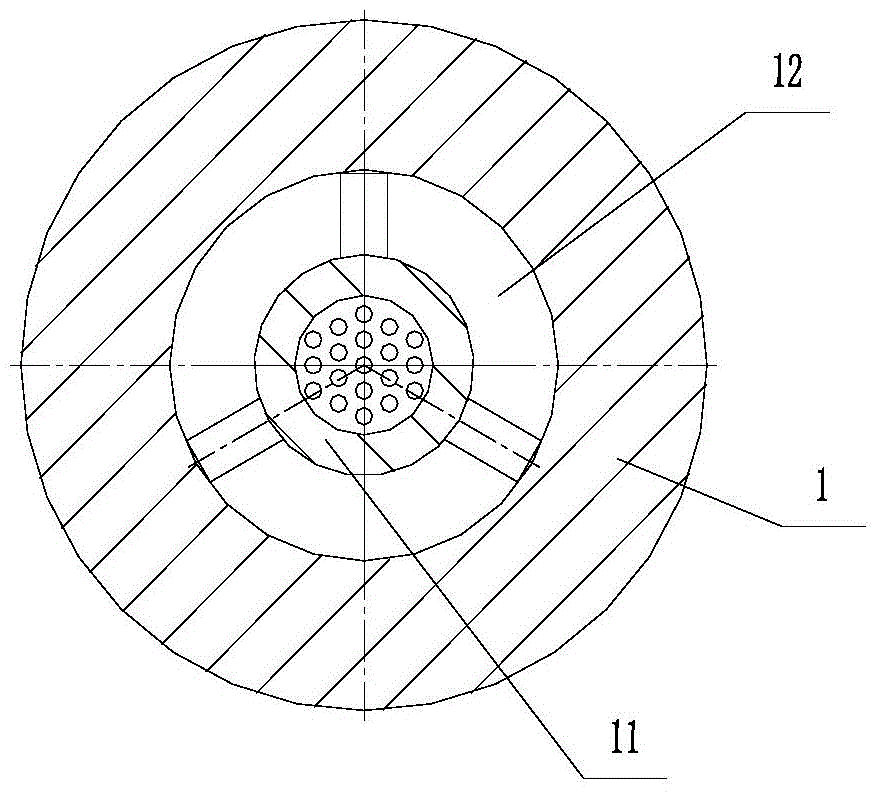
[0014] see figure 1 and figure 2 , a shear pin filter, including a cylinder 1 and a filter assembly installed inside it; the upper and lower ends of the cylinder 1 are provided with threads; the filter assembly includes a filter body 7, a centralizer 11, The hanging sleeve 5 and the limit sleeve 6 are fixedly connected with the centralizer 11 at the lower end of the filter body 7, and the centralizer 11 is slidably connected with the cylindrical body 1. Between the centralizer 11 and the filter An overflow channel 12 is formed between the bodies 1, and a filter hole 8 is provided on the centralizer 11 and the filter body 7; an annular space 10 is formed between the cylinder body 1 and the filter body 7, The upper end of the filter body 7 i...


PUM


Abstract

The invention discloses a shear pin filtrator. The shear pin filtrator comprises a barrel and a filtrator assembly arranged inside the barrel. The upper end and the lower end of the barrel are provided with threads. The filtrator assembly comprises a filtering body, a centering device, a hanging sleeve and a limiting sleeve. The lower end of the filtering body is fixedly connected with the centering device. The centering device is slidably connected with the barrel. An overflowing channel is formed between the centering device and the filtering body. Filtering holes are formed in the centering device and the filtering body. An annular space is formed between the barrel and the filtering body. The upper end of the filtering body is connected with the hanging sleeve through shear pins. The hanging sleeve is fixed inside the barrel. The upper end of the filtering body is provided with multiple pressure relieving holes which are evenly distributed in the circumferential direction. The shear pin filtrator has the advantages that the performance is reliable, the utilization is safe, harmful solidoids in mud can be removal by filtration, the safe and stable operation of downhole precise instruments is guaranteed, the labor intensity of working personnel can be lowered, the applicability is high, and the installation is convenient.

Description

technical field [0001] The invention relates to the technical field of oil and gas field drilling and completion, in particular to a shear pin filter used for drill pipes. Background technique [0002] At present, during offshore drilling operations, when the lower part of the drilling tool assembly carries precision instruments for operations (logging operations, directional well operations, etc.), these precision instruments have very high requirements for mud, so special equipment is required to filter the mud; and now Most of the 5-1 / 2" drill pipe fasteners used at sea are HT55 and most of the 5-7 / 8" drill pipe fasteners are XT57. These two fasteners have no space for conventional filter elements; at the same time, with the development of science and technology , most of the drilling platforms now use iron drillers to replace the derrick work in the past. When placing conventional filter elements in the drill pipe column, it is necessary to arrange special personnel to b...

Claims


Application Information

Patent Timeline
Patent Type & Authority Patents(China)
IPC IPC(8): E21B21/00
CPCE21B21/002
Inventor 刘禹铭朱益辉王玉山姚伟达刘洋马英明赵海杉李波
Owner CNOOC ENERGY TECH & SERVICES
Learn More