Engine oil-gas separation device with good oil-gas separation effect

A technology of separation device and oil and gas separation chamber, which is applied to engine components, machines/engines, mechanical equipment, etc., can solve the problems of low air flow speed of oil and gas separation device, unsatisfactory oil and gas separation effect, and difficult separation of oil molecules, and achieves oil-gas separation. The mist separation is complete, the structure is simple, and the effect of improving the phenomenon of oil burning

Inactive Publication Date: 2015-07-01
CHONGQING KAITE POWER SCI & TECH
View PDF9 Cites 1 Cited by
  • Summary
  • Abstract
  • Description
  • Claims
  • Application Information

AI Technical Summary

Problems solved by technology

[0002] At present, in the engine crankcase ventilation system, the structure of the oil-gas separator is various. They have one thing in common, that is, the gas directly enters the oil-gas separation device for oil-gas separation. The oil-gas pressure in the crankcase directly affects its separation effect. When the pressure is low , the airflow velocity entering the oil-gas separation device is low, the oil molecules are not easy to separate from the gas, the oil-gas separation effect is not ideal, part of the oil mist enters the combustion chamber, and the situation of burning engine oil occurs

Method used


Image

  • Engine oil-gas separation device with good oil-gas separation effect
  • Engine oil-gas separation device with good oil-gas separation effect
  • Engine oil-gas separation device with good oil-gas separation effect

Examples


Embodiment 1

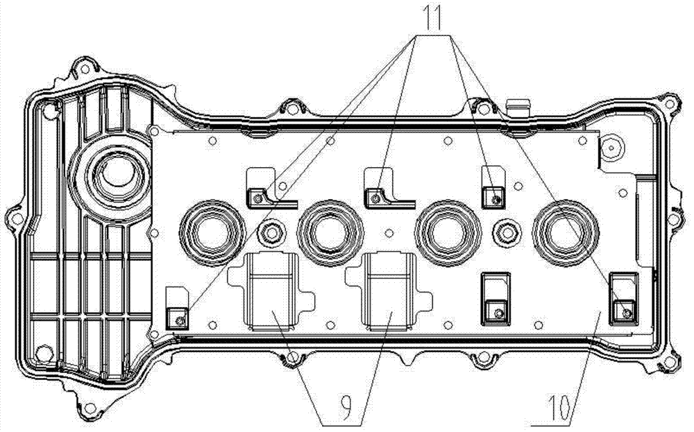
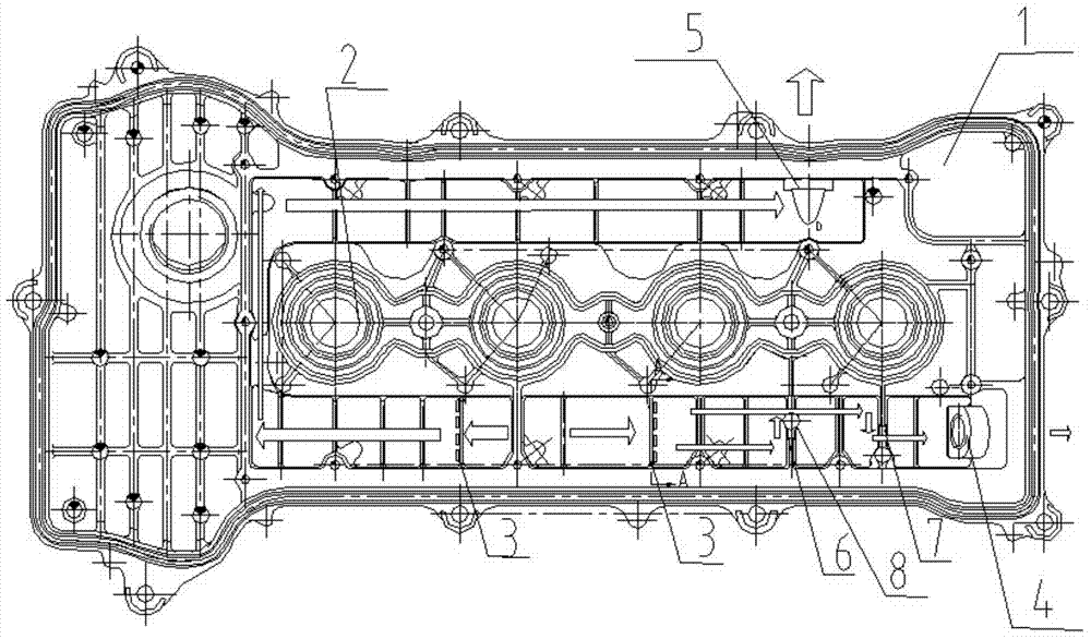
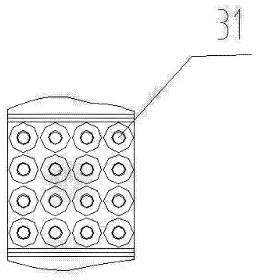
[0019] An engine oil-gas separation device with good oil-gas separation effect according to the present invention includes an oil-gas separation chamber, an acceleration device is arranged in the oil-gas separation chamber, and a through hole is arranged on the acceleration device, and the mixed gas enters the oil-gas separation after passing through the through hole The oil and gas are separated in the cavity, and the through hole is a tapered hole. Specifically: such as Figure 1-3 As shown: the engine oil-gas separation device with good oil-gas separation effect of the present invention includes a cylinder head cover body 1. A row of spark plug installation holes 2 is arranged in the middle of the cylinder head cover body 1 along the length direction, and the number of spark plug holes 2 is four, but not limited For four, the cylinder head cover body 1 is covered with a cylinder head cover oil-gas separation baffle 10, an oil-gas separation chamber is formed between the cyl...


PUM


Abstract

The invention discloses an engine oil-gas separation device with the good oil-gas separation effect. The engine oil-gas separation device comprises an oil-gas separation cavity, and is characterized in that an accelerating device is arranged in the oil-gas separation cavity, a through hole is formed in the accelerating device, mixed gas flows through the through hole and then enters the oil-gas separation cavity for oil-gas separation, and the through hole is a taper hole. The oil-gas separation efficiency is improved, and oil-mist separation is complete.

Description

technical field [0001] The invention relates to an engine oil-gas separation device with good oil-gas separation effect. Background technique [0002] At present, in the engine crankcase ventilation system, the structure of the oil-gas separator is various. They have one thing in common, that is, the gas directly enters the oil-gas separation device for oil-gas separation. The oil-gas pressure in the crankcase directly affects its separation effect. When the pressure is low , the airflow velocity entering the oil-gas separation device is low, the oil molecules are not easy to separate from the gas, the oil-gas separation effect is not ideal, part of the oil mist enters the combustion chamber, and the situation of burning engine oil occurs. Contents of the invention [0003] In view of the existing problems, the object of the present invention is to provide an engine oil-gas separation device with good oil-gas separation effect. [0004] In order to achieve the above objec...

Claims


Application Information

Patent Timeline
Patent Type & Authority Applications(China)
IPC IPC(8): F01M13/04
Inventor 白天明延虎和艳萍张志义陆银华
Owner CHONGQING KAITE POWER SCI & TECH
Why Eureka
Try Eureka