Rolling bearings and spindle devices for machine tools

一种滚动轴承、转动体的技术,应用在滚子轴承、轴和轴承、轴承元件等方向,能够解决滚动轴承易发生异常升温等问题,达到缩短试运行时间、抑制异常升温的效果

Active Publication Date: 2017-08-08
NSK LTD
View PDF3 Cites 0 Cited by
  • Summary
  • Abstract
  • Description
  • Claims
  • Application Information

AI Technical Summary

Problems solved by technology

However, in the case of excessive lubricant, rolling bearings are prone to abnormal temperature rise

Method used


Image

  • Rolling bearings and spindle devices for machine tools
  • Rolling bearings and spindle devices for machine tools
  • Rolling bearings and spindle devices for machine tools

Examples


no. 1 approach

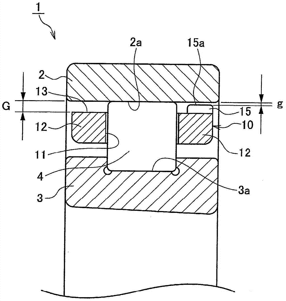
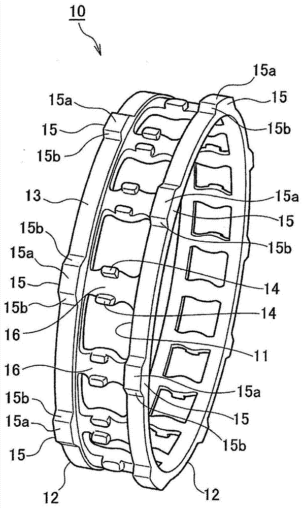
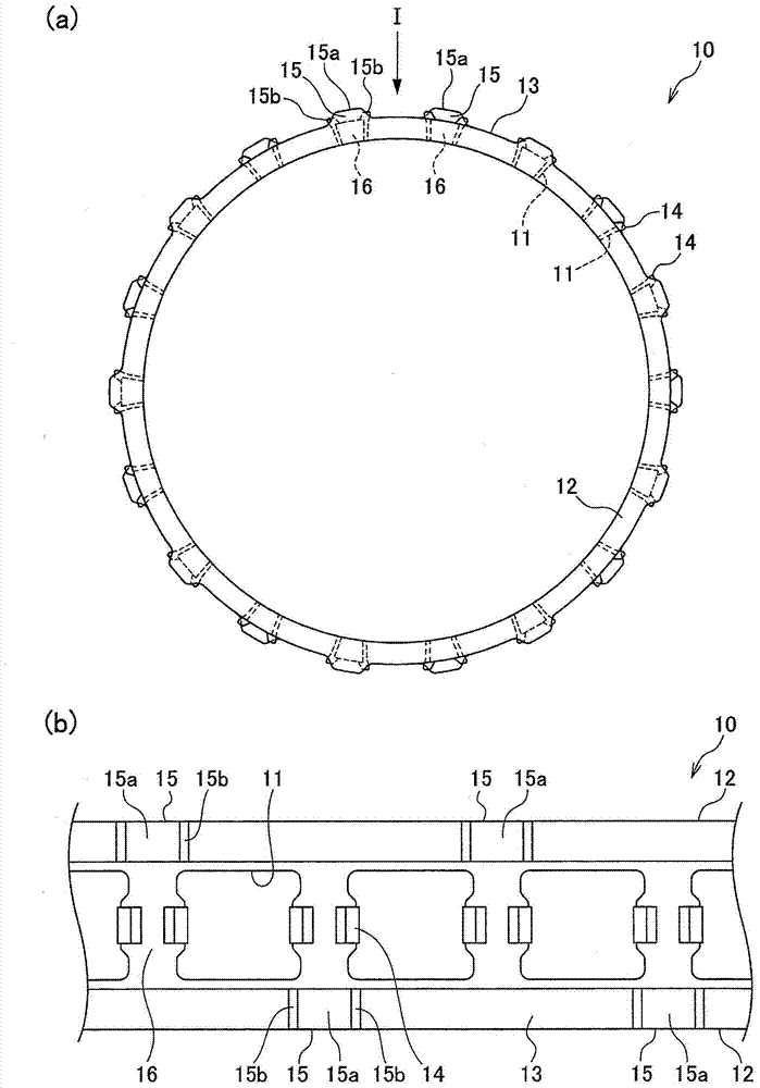
[0045] Below, according to figure 1 A rolling bearing according to a first embodiment of the present invention will be described. figure 1 A sectional view showing the cylindrical roller bearing 1 of the first embodiment. figure 2 express figure 1 A perspective view of the cage 10 in . image 3 express figure 2 The cage 10 in, wherein, (a) is a front view of the cage 10, and (b) is a partial top view viewed from the I direction of (a).

[0046] Such as figure 1 As shown, the cylindrical roller bearing 1 has: an outer ring 2 with an outer ring raceway surface 2a formed on the inner peripheral surface; an inner ring 3 with an inner ring raceway surface 3a formed on the outer peripheral surface; a cylindrical roller 4; and a cage 10 disposed between the outer ring 2 and the inner ring 3. A plurality of pockets 11 are formed in the cage 10 , and a plurality of cylindrical rollers 4 are held in each pocket 11 to be able to roll freely.

[0047] Such as figure 2 As sh...

no. 2 approach

[0052] Below, according to Figure 4 A rolling bearing according to a second embodiment of the present invention will be described. Figure 4 The cage 20 used in the cylindrical roller bearing of the second embodiment is shown, (a) is a front view of the cage 20, and (b) is a partial plan view of (a) seen from the II direction.

[0053] The cage 20 used in the second embodiment, like the cage 10 used in the first embodiment, has: a pair of annular portions 22 arranged side by side in the axial direction; A plurality of column portions 26 arranged at predetermined intervals in the circumferential direction in a connected manner. The pocket 21 is formed by a pair of annular portions 22 and two column portions 26 adjacent in the circumferential direction. In addition, roller stoppers 24 are provided on both sides in the circumferential direction of the axially intermediate portion of the column portion 26 so as to protrude from the outer peripheral surface of the column portion...

no. 3 approach

[0057] Next, according to Figure 5 A third embodiment of the present invention will be described. Figure 5 The cage 30 used for the radial thrust ball bearing of the third embodiment is shown, wherein (a) is a front view of the cage 30, and (b) is a partial plan view seen from the direction III in (a) .

[0058] Same as the cage 10 used in the first embodiment, Figure 5 The cage 30 shown has: a pair of annular portions 32 arranged in parallel in the axial direction; and a plurality of column portions 36 arranged at predetermined intervals in the circumferential direction so as to connect the two annular portions 32 . The pocket 31 is formed by a pair of annular portions 32 and two column portions 36 adjacent in the circumferential direction.

[0059] On the outer peripheral surface 33 of the pair of annular portions 32, a plurality of convex protrusions 35 having a diameter larger than the outer peripheral surface of the column portion 36 are formed at predetermined inte...


PUM


Abstract

The present invention provides a rolling bearing and a spindle device for a machine tool capable of suppressing an abnormal temperature rise of the rolling bearing and shortening the time required for a test run during grease lubrication by improving lubricant discharge properties. The cage (10) used in the rolling bearing of the present invention has: a pair of annular parts (12) arranged in parallel in the axial direction; A plurality of column parts (16). Each annular portion (12) has a plurality of convex protrusions (15) separately formed on the respective outer peripheral surface (13) along the circumferential direction. The convex protrusion (15) of one annular portion (12) is formed at a different position in the circumferential direction from the convex protrusion (15) of the other annular portion (12).

Description

technical field [0001] The present invention relates to a rolling bearing and a spindle device for a machine tool, and more specifically, to a rolling bearing used for a high-speed rotating machine tool spindle, a high-speed motor, and the like, and a machine tool spindle device using the rolling bearing. Background technique [0002] In recent years, in order to efficiently process bearings used in machine tool spindle units, speeding up has been promoted. If the discharge performance of the lubricant is deteriorated in the bearing rotating at high speed, there will be too much lubricant, and abnormal heat will be generated due to the generation of stirring heat. In such a case, the temperature of the bearing rises abnormally, which may cause damage to the bearing. [0003] Figure 10 is a conventional cylindrical roller bearing 100 . Cylindrical roller bearing 100 has: outer ring 102 with outer ring raceway 102a on the inner peripheral surface; inner ring 103 with inner ...

Claims


Application Information

Patent Timeline
Patent Type & Authority Patents(China)
IPC IPC(8): F16C33/46F16C33/66
CPCF16C33/4605F16C33/4676F16C33/4682F16C33/6622F16C33/6629B23Q1/70F16C19/26F16C2322/39F16C33/46B23Q11/12F16C33/66
Inventor 水上敦司
Owner NSK LTD
Why Eureka
Try Eureka