Chemical dosing device and control method thereof

A technology of dosing device and controller, applied in feeding device, chemical instrument and method, flotation and other directions, can solve the problem of not considering the influence of flow rate, etc., and achieve the effect of improving service life and improving dosing stability.

Pending Publication Date: 2018-06-29
JIANGXI NERIN ELECTRIC AUTOMATION
View PDF0 Cites 0 Cited by
  • Summary
  • Abstract
  • Description
  • Claims
  • Application Information

AI Technical Summary

Problems solved by technology

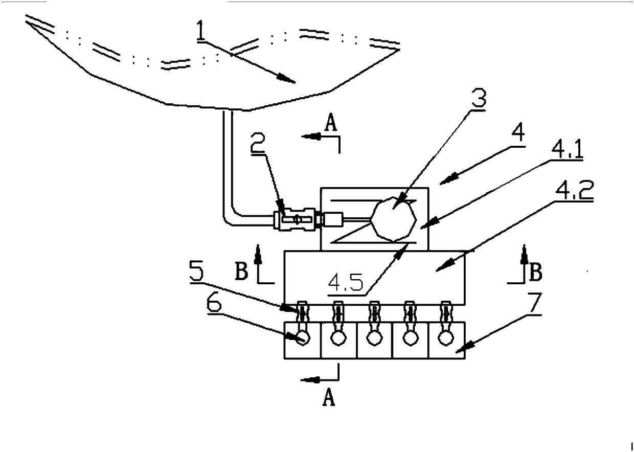
[0004] PLC electromagnetic valve type dosing machine has also appeared on the market now, which has better solved the service life problem of control elements and adding devices, but its constant pressure device has selected a column type float valve and still does not solve the problem of liquid at the front end of the electromagnetic valve. The problem of surface stability; the working principle of the solenoid valve is the constant frequency variable pulse width method. This method does not consider the influence of the change of the orifice section on the flow rate when the solenoid valve closes and opens. When the pulse width is longer (large flow rate is added) The flow has little effect, but the impact on the actual flow is more serious for the pulse width is very narrow (when the small flow is added)

Method used


Image

  • Chemical dosing device and control method thereof
  • Chemical dosing device and control method thereof
  • Chemical dosing device and control method thereof

Examples


Embodiment Construction

[0024] Embodiments of the present invention are described in detail below, examples of which are shown in the drawings, wherein the same or similar reference numerals designate the same or similar elements or elements having the same or similar functions throughout. The embodiments described below by referring to the figures are exemplary only for explaining the present invention and should not be construed as limiting the present invention.

[0025] In describing the present invention, it should be understood that the terms "center", "longitudinal", "transverse", "upper", "lower", "front", "rear", "left", "right", " The orientations or positional relationships indicated by "vertical", "horizontal", "top", "bottom", "inner" and "outer" are based on the orientations or positional relationships shown in the drawings, and are only for the convenience of describing the present invention and Simplified descriptions, rather than indicating or implying that the device or element refe...


PUM


Abstract

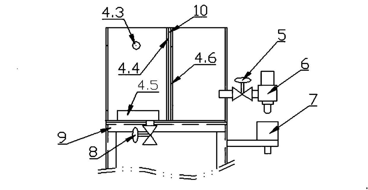
The invention discloses a chemical dosing device and a control method thereof. The chemical dosing device comprises a chemical constant-pressure tank, a chemical dosing electromagnetic valve and a controller, wherein the chemical constant-pressure tank is of a closed tank body; a chemical inlet is formed in the tank; a float valve is arranged at the chemical inlet; the chemical dosing electromagnetic valve is arranged on the chemical constant-pressure tank and used for releasing a chemical from the chemical constant-pressure tank according to a pulse control signal sent by the controller; thecontroller is used for generating the pulse control signal according to a required chemical amount per unit time and sending the pulse control signal to the chemical dosing electromagnetic valve, so as to control the chemical dosing electromagnetic valve to release the required chemical from the chemical constant-pressure tank. The chemical dosing device disclosed by the invention has the following advantages that: the chemical constant-pressure tank ensures that pressure at an outlet of a valve is constant; the chemical constant-pressure tank is periodically opened and closed through the chemical dosing electromagnetic valve in a fixed-pulse-width variable-frequency manner, so as to accurately control the chemical flow and improve the chemical dosing stability; valve parameters are corrected in the fixed-pulse-width variable-frequency manner to strictly restrain an action frequency of the chemical dosing electromagnetic valve to avoid an abnormal temperature rise and prolong the service life of the chemical dosing electromagnetic valve.

Description

technical field [0001] The invention relates to the technical field of dosing equipment, in particular to a dosing device and a control method thereof. Background technique [0002] The dosing system is widely used in non-ferrous metal beneficiation, extraction and other production processes that require quantitative addition of liquid chemicals. The veneer dosing machine appeared in large-scale mineral processing plants in China in the late 1980s and was widely used for reference by other mineral processing plants. Its advantage is that it replaces manual or measuring instruments, and realizes constant automatic dosing with a single-chip microcomputer as the core, and the flow rate is adjusted. There is no need to manually interfere with the valve or measuring cup of the equipment, and only need to set the flow rate on the input operator provided by the equipment, but its shortcomings are also obvious. The single-chip microcomputer is mainly based on the printed circuit boa...

Claims


Application Information

Patent Timeline
Patent Type & Authority Applications(China)
IPC IPC(8): B01J4/02C22B3/02B03D1/001B03D1/14
CPCB01J4/008B01J4/02B01J2204/002B03D1/001B03D1/145C22B3/02Y02P10/20
Inventor 喻仁盛文辉煌周忠光
Owner JIANGXI NERIN ELECTRIC AUTOMATION
Why Eureka
Try Eureka