Rotary vibratory force head main shaft device

A technology of spindle device and vibration force, which is applied in the direction of driving device, bearing elements, shafts and bearings of rotary combined drilling, can solve the problems of poor ability to withstand alternating stress, difficult assembly and adjustment, and complicated force, and achieve bearing capacity The effect of strong alternating stress ability, simple and reasonable structure, and convenient assembly and adjustment

Inactive Publication Date: 2015-07-01
YUNNAN LAND & RESOURCES VOCATIONAL COLLEGE
View PDF8 Cites 2 Cited by
  • Summary
  • Abstract
  • Description
  • Claims
  • Application Information

AI Technical Summary

Problems solved by technology

Due to the complexity and variability of its force, it poses new challenges to the design and research of the main shaft structure
[0003] At present, most manufacturers use short cylindrical roller bearings or centripetal plane bearings for the main shaft support of rotary vibratory heads, which have poor ability to withstand alternating stress and are difficult to assemble and adjust.

Method used


Image

  • Rotary vibratory force head main shaft device
  • Rotary vibratory force head main shaft device

Examples


Embodiment Construction

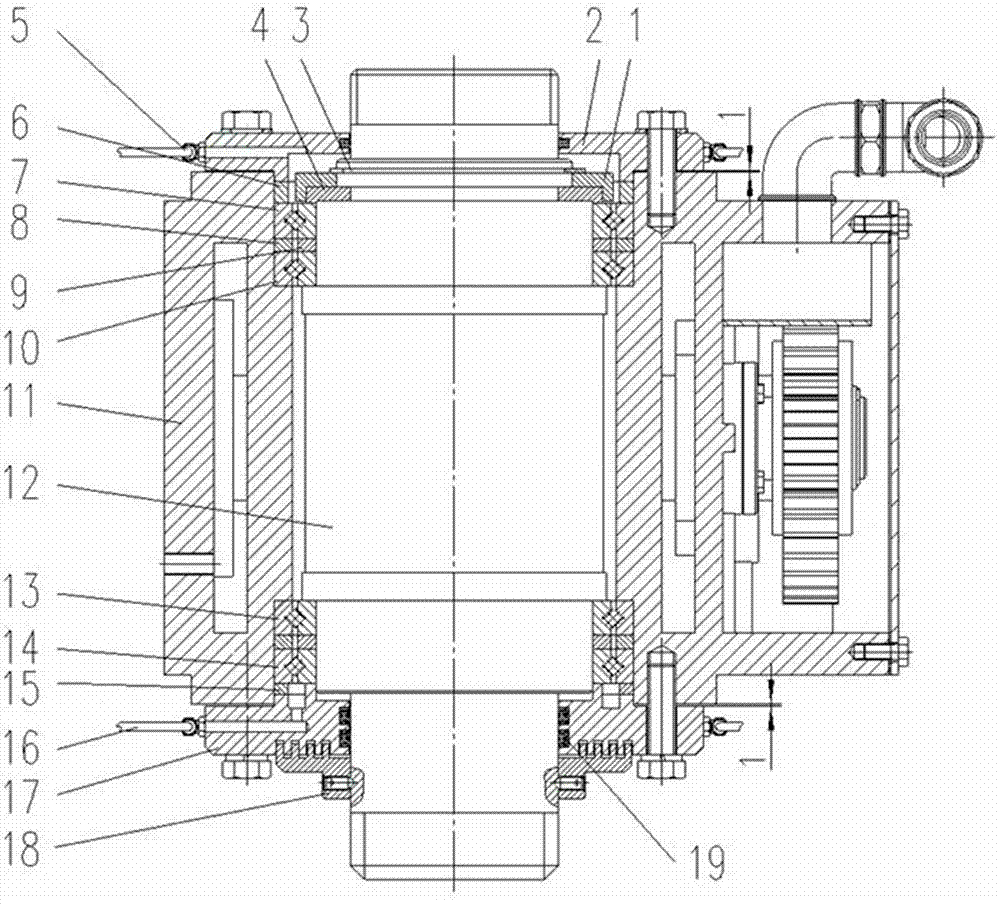
[0014] like figure 1 As shown, the rotary vibrating head spindle device of the present invention includes a spindle 12 installed in a spindle housing 11 . An upper pair of crossed roller bearings and a lower pair of crossed roller bearings are installed on the upper journal and the lower journal of the main shaft respectively. The inner end surface of the inner ring of the inner crossed roller bearing 10 in the upper crossed roller bearing pair is in contact with the end surface of the upper shaft journal, and the inner end surface of the inner ring of the inner crossed roller bearing 13 in the lower crossed roller bearing pair is in contact with the end surface of the lower shaft journal. The ends of the neck are fitted. The outer end surface of the inner ring of the outer crossed roller bearing 7 in the upper crossed roller bearing pair is locked in turn by the retaining ring 4, the hoop 1 and the shaft circlip 3, and the outer ring is locked by the upper gland 2 and the lo...


PUM


Abstract

The invention discloses a rotary vibratory force head main shaft device. Shaft necks at the upper and lower ends of a main shaft are respectively provided with upper and lower crossed roller bearing pairs, wherein the inner end surface of an inner ring of an inner crossed roller bearing in each crossed roller bearing pair is adhered to the end surfaces of the shaft necks of the main shaft, the outer end surface of an inner ring of an outer crossed roller bearing in the upper crossed roller bearing pair is locked successively by virtue of a holding loop, a hoop and a circlip for a shaft so a to be locked, and an outer ring of the outer crossed roller bearing is locked by virtue of an upper gland and a locknut; the outer ring and inner ring of the outer crossed roller bearing in the lower crossed roller bearing pair are respectively locked by virtue of a lower gland and a locknut, the outer end of the lower gland is provided with a labyrinth sealing ring, and the upper gland and the lower gland are respectively provided with an upper oil passage and a lower oil passage. The rotary vibratory force head main shaft device is high in alternating stress endurance capacity, convenient to assemble, adjust and replace, and capable of improving the working stability of a rotary vibratory force head.

Description

technical field [0001] The invention relates to the technical field of drilling machinery, in particular to the technical field of the main shaft structure of a drilling power head. Background technique [0002] Rotary vibrating head is a common component of construction equipment such as drilling. It has the function of rotation and vibration, and is widely used in foundation pile holes or large-diameter drilling construction machinery. The main shaft part is the core mechanism of the rotary vibratory head. Its lower end is connected with the drill pipe, and its upper end is connected with the reducer. It is the main force transmission or force receiving part in the drilling process. Its accuracy directly affects the drilling diameter and straightness. Its reliability directly restricts the working life of the whole machine. Due to the complexity and variability of its force, it poses new challenges to the design and research of the main shaft structure. [0003] At prese...

Claims


Application Information

Patent Timeline
Patent Type & Authority Applications(China)
IPC IPC(8): F16C35/12F16J15/16F16N1/00E21B6/00
Inventor 秦忠崔庆权蒋芳邹艳红陈家文陈伟唐瑜谦王昆何绍昆许芬陈军浦仕聪文富强
Owner YUNNAN LAND & RESOURCES VOCATIONAL COLLEGE
Why Eureka
Try Eureka