A reed lock bar

A piece lock and tight strip technology, applied in the field of reed lock strips, can solve the problems of electrical conductivity, vertical insertion, etc., achieve reliable electrical conductivity, prevent flipping, and have a wide range of application prospects

Active Publication Date: 2017-03-01
江苏雷兹盾材料科技有限公司
View PDF7 Cites 0 Cited by
  • Summary
  • Abstract
  • Description
  • Claims
  • Application Information

AI Technical Summary

Problems solved by technology

[0005] In order to overcome the problems existing in the prior art, the present invention provides a reed locking strip, which not only overcomes the problem of electrical conductivity, but also solves the problem of vertical insertion by adopting a newly designed simple structure

Method used


Image

  • A reed lock bar
  • A reed lock bar
  • A reed lock bar

Examples


Embodiment

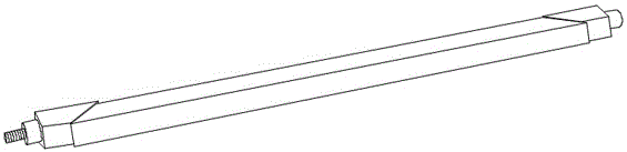
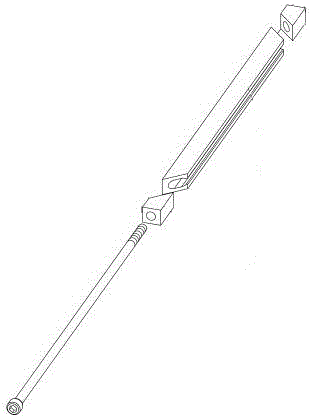
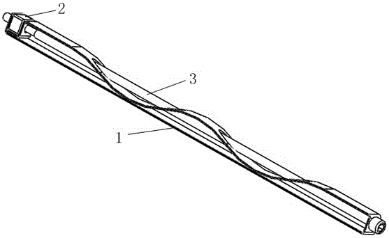
[0032] Such as Figure 3 to Figure 7 As shown, the reed locking strip is mainly used for the clamping and installation of the chassis and board modules of military equipment, especially in environments requiring high electrical conductivity. Usually, the locking strip is installed in the preset installation groove for The board module can be clamped to keep it stably in the chassis. When the board fails or needs maintenance, just adjust and loosen the locking bar to take off the board. Due to the design defect of the existing locking bar structure, if the power tool is used to disassemble, it is easy to cause the end wedge to fall, which will cause the short circuit of the board card circuit to fail, and when the locking bar is inserted and pulled in the vertical direction, it will be damaged due to gravity. The effect makes the wedge part open at the maximum width, which seriously affects the insertion of the board and greatly increases the difficulty of board insertion. The ...


PUM


Abstract

The invention discloses a novel spring plate locking strip. The novel spring plate locking strip comprises an integral spring plate clamping part, an overturning preventing nut mounted at one end of the spring plate clamping part, and an adjusting bolt which passes through the spring plate clamping part and is connected with the overturning preventing nut, wherein the spring plate clamping part comprises a limiting bottom plate, an end limiting part, an end connecting part, a clamping connecting part, an elastic clamping body, an inner limiting part, and a through hole formed in the corresponding part; at least one wave shaped bulge back to the limiting bottom plate is formed on the elastic clamping body due to the undulating times of the elastic clamping body. The novel spring plate locking strip is ingenious in ideal; the integrally formed spring plate clamping part can replace a wedge shaped part in the original structure; a board block can be clamped under the elasticity effect of the elastic clamping body; such integral structure ensures reliable conductivity, and moreover, the opposite moving of the original wedge-shaped part is replaced; the locking strip can be effectively prevented from overturning; meanwhile, the original wedge-shaped part can be actively opened during vertical inserting and drawing, and thus the inserting influence is reduced.

Description

technical field [0001] The invention relates to a locking strip, in particular to a reed locking strip. Background technique [0002] With the development of science and technology, the design of military equipment is increasingly inclined to miniaturization, integration and modularization. The first problem to be solved by military equipment is the vibration problem. How to ensure that the connection between the module and the motherboard does not fail under the condition of high-speed impact has always been the direction of connector efforts. The emergence of the locking strip as a structural part to improve the seismic strength of the board greatly reduces the difficulty of connector development. Therefore, there are more and more application environments for locking strips, from tanks and armored vehicles to various ships, to civil and military aircraft, to aerospace equipment. [0003] A high degree of integration also requires that the current equipment be maintaine...

Claims


Application Information

Patent Timeline
Patent Type & Authority Patents(China)
IPC IPC(8): F16F1/26
CPCF16F1/26
Inventor 鄢登俊
Owner 江苏雷兹盾材料科技有限公司
Why Eureka
Try Eureka