Mining intrinsically safe type electric ball valve

An intrinsically safe, electric ball valve technology, applied in the valve details, valve device, valve shell structure, etc., can solve the problems of manufacturing and installation trouble, circuit disorder, waste of resources, etc., to ensure stability and reliability, electrical connection The effect of shortening the line and avoiding the waste of resources

Active Publication Date: 2015-07-01
重庆圣皓机械设备制造集团有限公司
View PDF12 Cites 8 Cited by
  • Summary
  • Abstract
  • Description
  • Claims
  • Application Information

AI Technical Summary

Problems solved by technology

But this patent scheme still has the following shortcomings: First, because it is independently arranged in the shell cavity of the housing by the way of separating the control circuit board and the fixed plate (the patent is called the first fixed plate), thus on the one hand, the structural Complexity and a large number of parts, on the one hand, cause troubles for manufacturing and installation, and cause waste of resources on the other hand; second, because the distance between the control circuit board and the signal collector is relatively large, not only the control circuit board and the signal acquisition mechanism The electrical connection lines between them are lengthy, and it is easy to cause line disorder, which affects the stability and reliability of the work; third, because it does not have the function of revealing the working position or working state of the electric ball valve, it is impossible to intuitively understand the electric ball valve. Open, closed and semi-open states of ball valves

Method used


Image

  • Mining intrinsically safe type electric ball valve

Examples


Embodiment Construction

[0019] In order to enable the examiners of the patent office, especially the public, to understand the technical essence and beneficial effects of the present invention more clearly, the applicant will describe in detail the following in the form of examples, but none of the descriptions to the examples is an explanation of the solutions of the present invention. Any equivalent transformation made according to the concept of the present invention which is merely formal but not substantive shall be regarded as the scope of the technical solution of the present invention.

[0020] In the following descriptions, all concepts involving up, down, left, right, front and rear directionality (or orientation) are for the position state of the picture being described, and the purpose is to facilitate the public Therefore, it cannot be understood as a special limitation on the technical solution provided by the present invention.

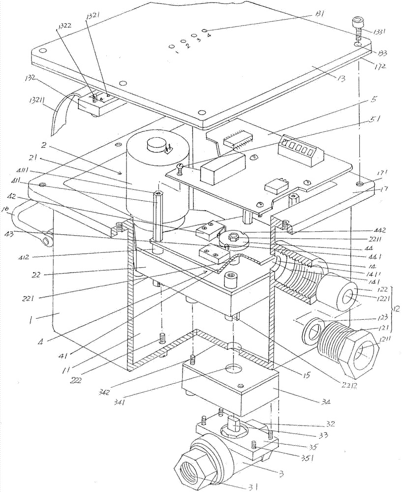
[0021] See figure 1 , provides: a housing 1 with a shel...


PUM


Abstract

The invention discloses a mining intrinsically safe type electric ball valve, and belongs to the technical field of coal mining safety facilities. The mining intrinsically safe type electric ball valve comprises a shell, a ball valve opening and closing mechanism, an electric ball valve body, a signal collecting mechanism and a control circuit board, wherein the shell is provided with an external power supply lead-in device, the electric ball valve body is arranged on one side of the bottom wall of the shell, the signal collecting mechanism is arranged in a shell cavity, the control circuit board is arranged in the shell cavity, and the ball valve opening and closing mechanism comprises a motor and a reduction gearbox. The mining intrinsically safe type electric ball valve is characterized in that the signal collecting mechanism comprises a signal collecting device positioning plate, a first signal collector, a second signal collector and a signal collector trigger plate, the upward side of the signal collector positioning plate is provided with a set of control circuit board supporting columns, the control circuit board is fixed to the tops of the control circuit board supporting columns, a shell protection cover is fixed to the shell and provided with a set of indicator lamp holes, indicator lamp bases are fixed to the side, facing the control circuit board, of the shell protection cover, and a set of indicator lamps are arranged on the indicator lamp bases. The structure is simplified, manufacturing and installing are convenient, and materials are saved; the working stability and reliability are ensured; the working state of the electric ball valve can be revealed.

Description

technical field [0001] The invention belongs to the technical field of coal mine safety facilities, and in particular relates to a mine-used intrinsically safe electric ball valve. Background technique [0002] As the industry knows, in coal mines, coal dust is one of the most harmful hidden dangers. In view of this, automatic spraying and watering dust suppression devices are usually installed in mining work areas, coal transportation and transfer areas, and other places where a large amount of coal dust can be generated. , so as to play the role of dust prevention and dust removal, to ensure the personal safety of miners and avoid the loss of coal mine facilities. Because when the concentration of coal dust, i.e. floating dust, in the air is seriously exceeding the standard and tends to be saturated, it will cause an explosion if it encounters an open flame or static electricity. The same applies to other industries such as metal mines or non-metal mines. [0003] The a...

Claims


Application Information

Patent Timeline
Patent Type & Authority Applications(China)
IPC IPC(8): F16K31/04F16K27/06F16K5/06F16K37/00
CPCF16K5/06F16K27/067F16K31/043F16K37/0025
Inventor 沈国平朱金权
Owner 重庆圣皓机械设备制造集团有限公司
Why Eureka
Try Eureka