Satellite-borne cable-net-foldable antenna profile accuracy measurement method

An accuracy measurement and antenna technology, which is applied in the field of cable-net type deployable antenna shape and surface accuracy measurement, can solve the problems of large influence of environmental factors, low measurement accuracy, and large workload, and achieves low measurement cost, high measurement accuracy, and high cost. less time effect

Active Publication Date: 2015-07-01
XIDIAN UNIV
View PDF5 Cites 10 Cited by
  • Summary
  • Abstract
  • Description
  • Claims
  • Application Information

AI Technical Summary

Problems solved by technology

[0012] The purpose of the present invention is to propose a new type of non-contact measurement method for the current situation of measuring the accuracy of the reflective surface of the deployable antenna, which can effectively solve the problems of low measurement accuracy, high cost, heavy workload and environmental factors. big problem

Method used


Image

  • Satellite-borne cable-net-foldable antenna profile accuracy measurement method
  • Satellite-borne cable-net-foldable antenna profile accuracy measurement method
  • Satellite-borne cable-net-foldable antenna profile accuracy measurement method

Examples


Embodiment 1

[0044] A method for measuring the shape and surface accuracy of a spaceborne cable-net deployable antenna in this embodiment includes the following steps in sequence, such as figure 1 Shown:

[0045] Step 1) Evenly arrange code points on the surface of the deployable antenna, and the number of code points is greater than 4.

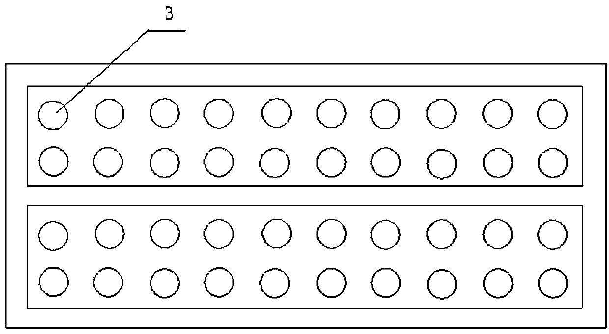
[0046] Step 2) Arranging marker points 3 at each node on the surface of the deployable antenna 1 .

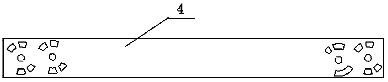
[0047] Step 3) Place two measuring scales 4 around the deployable antenna 1, and the two measuring scales 4 are placed non-parallel.

[0048] Step 4) adjust digital camera parameters;

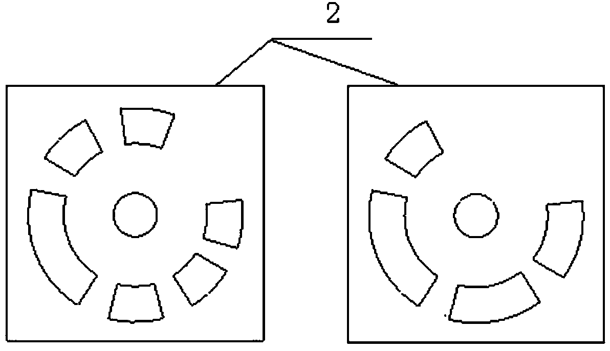
[0049] Step 5) Take a picture of the expandable antenna with a hand-held digital camera around the antenna. When taking pictures, the previous picture and the next picture have a common code point;

[0050] Step 6) Import the photo into the photogrammetry device, and solve the three-dimensional coordinates of each marker point and code point;

[0051] Step 7) process th...

Embodiment 2

[0078] This embodiment is a specific measurement example, taking the measurement of a certain 2m diameter deployable antenna 1 as an example, the measurement steps are as follows figure 1 shown.

[0079] Step 1) Evenly arrange code points on the surface of the deployable antenna, and the number of code points is greater than 4.

[0080] Step 2) Arranging marker points 3 at each node on the surface of the deployable antenna 1 .

[0081] Step 3) Place two measuring scales 4 around the deployable antenna 1, and the two measuring scales 4 are placed non-parallel.

[0082] After the above three steps are completed, the effect is as follows: Figure 8 shown.

[0083] Step 4) Adjust digital camera parameters.

[0084] Step 5) Take a picture of the deployable antenna 1 with a hand-held digital camera around the antenna 1, and the previous picture and the next picture have a common code point 2 when taking pictures.

[0085] Step 6) Import the photos into the photogrammetry device...


PUM


Abstract

The invention discloses a satellite-borne cable-net-foldable antenna profile accuracy measurement method. The method specifically includes the following steps of preparation work conducted before antenna measurement, picture taking, measuring point coordinate calculation achieved by leading in a measurement device, coordinate conversion, surface fitting, and antenna profile accuracy calculation. The method is high in measuring efficiency and speed, and one-time measurement time of a cable net type foldable antenna is about one hour; devices are convenient to use and easy to disassemble and assemble, and less time is spent on the early-stage preparation work; non-contact type measurement is conducted, and no direct contact with the reflection face of the antenna is needed in the measurement process; the measurement stability is high. The method is not prone to interference of environment factors; the measurement accuracy is high, the maximum measurement error is 0.2 mm, and the measurement requirement of the foldable antenna can be completely met; compared with other measurement methods, the measurement cost is low.

Description

technical field [0001] The present invention relates to a method for measuring the accuracy of an antenna, in particular to a method for measuring the shape and surface accuracy of a cable-net type deployable antenna. Background technique [0002] The surface accuracy of the antenna reflector is one of the main mechanical performance indicators of the antenna structure, and it is closely related to the shortest working wavelength of the antenna. The quality of the surface accuracy will directly affect the working efficiency of the antenna. [0003] The deployable antenna is a special space structure, and its working environment has high requirements on the shape and surface accuracy of the antenna. Therefore, it is particularly important to measure the shape and surface accuracy of deployable antennas. [0004] In general, an ideal method for measuring the surface accuracy of deployable antennas should have the following characteristics: [0005] (1) The measuring device ...

Claims


Application Information

Patent Timeline
Patent Type & Authority Applications(China)
IPC IPC(8): G01B21/20
CPCG01B11/24
Inventor 杨东武高扬段宝岩
Owner XIDIAN UNIV
Why Eureka
Try Eureka