
Laser radar three-dimensional scanning rotating mirror system

A technology of three-dimensional scanning and rotating mirror system, which is applied in radio wave measurement system, re-radiation of electromagnetic waves, utilization of re-radiation, etc., can solve the problems of increased hardware cost, large volume and bulky scanning rotating mirror, etc., to save hardware cost, The effect of reducing size and weight

Active Publication Date: 2015-07-01
SHENZHEN DARSUN LASER TECH CO LTD
View PDF5 Cites 3 Cited by
  • Summary
  • Abstract
  • Description
  • Claims
  • Application Information

AI Technical Summary

Problems solved by technology

Traditional radar scanning mirrors are bulky and cumbersome, and cannot be applied to small wind measuring radars
Some of the small coherent wind radars launched on the market in the early stage can only achieve azimuth rotation, but cannot change the elevation angle at the same time, and the other part is just the opposite, that is, it cannot realize vertical and horizontal three-dimensional scanning at the same time
The lidar scanning mirror provided by the prior art is bulky and cumbersome
Moreover, the drive motor for controlling the pitch, the pitch reducer and the pitch synchronous gear train are all installed in the main mirror housing, which has a complex structure and is difficult to manufacture and install. In order to maintain the balance of the pitch rotating mirror, it is necessary to add structural modules on the symmetrical plane
Since both the motor and the reducer need power supply, an electric slip ring (or slip ring) must be used, which increases the hardware cost

Method used


Image

  • Laser radar three-dimensional scanning rotating mirror system
  • Laser radar three-dimensional scanning rotating mirror system

Examples


Embodiment Construction

[0014] In order to better understand the technical solutions of the present invention, the embodiments provided by the present invention will be described in detail below in conjunction with the accompanying drawings.

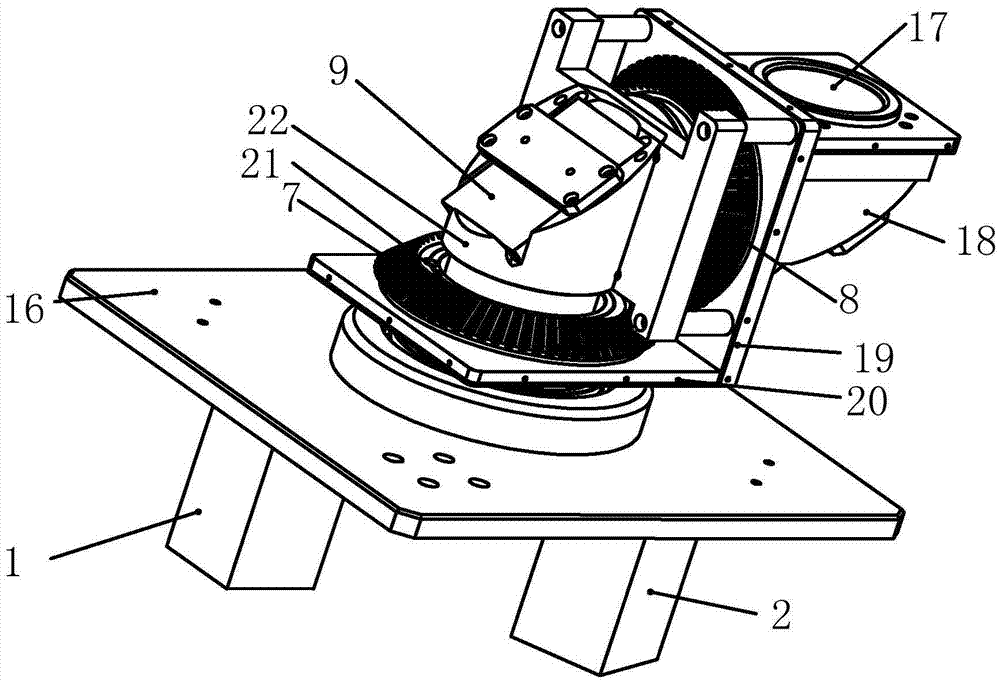
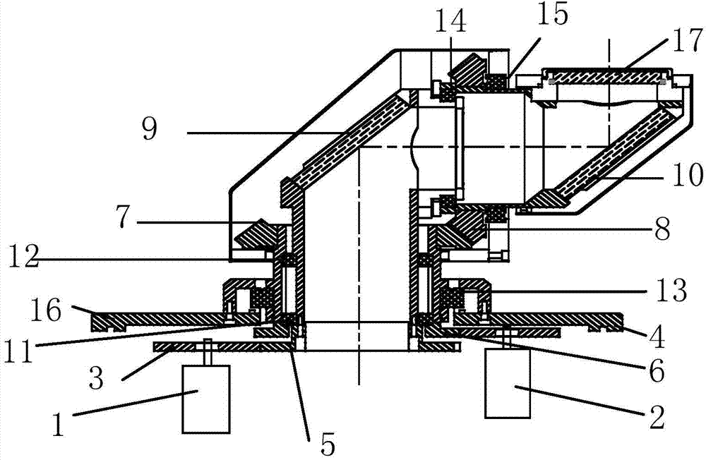
[0015] An embodiment of the present invention provides a laser radar three-dimensional scanning rotating mirror system, such as figure 1 with figure 2 As shown, it includes: pitch mirror frame 18, azimuth mirror frame 22, support base plate 16, pitch bevel gear 8, transmission bevel gear 7, L-shaped bevel gear frame, pitch motor 2 and azimuth motor 1, wherein:

[0016] Described pitch motor 2 and azimuth motor 1 are arranged on the below of support base plate 16, and described pitch mirror frame 18, azimuth mirror frame 22, pitch bevel gear 8, transmission bevel gear 7, L-shaped bevel gear frame are arranged on support base plate 16 Above, the pitching bevel gear 8 and the transmission bevel gear 7 are perpendicular to each other, and the teeth on the edges m...


PUM


Abstract

The invention provides a laser radar three-dimensional scanning rotating mirror system comprising a pitching motor and an azimuth motor. The pitching motor and the azimuth motor are disposed below a support bottom plate. A pitching mirror carrier, an azimuth mirror carrier, a pitching bevel gear, a transmission bevel gear and an L-shaped bevel gear are disposed above the support bottom plate; the pitching bevel gear is perpendicular to the transmission bevel gear and meshes with the same; the pitching bevel gear is parallelly mounted on the side of a vertical plate of the bevel gear carrier; a first spindle of the pitching mirror carrier penetrates the vertical plate and is fixedly connected with the pitching bevel gear; the transmission bevel gear is parallelly mounted above a transverse plate of the bevel gear carrier; the transmission bevel gear is in transmission connection with the pitching motor; an azimuth mirror is disposed at the upper end of the azimuth mirror carrier; the upper portion of the azimuth mirror carrier is fixedly connected with a side plate of the bevel gear carrier. The laser radar three-dimensional scanning rotating mirror system has the advantages that the size and weight of the system is greatly reduced, hardware cost is saved, and three-dimensional continuous scanning is available.

Description

technical field [0001] The invention relates to the technical field of laser equipment, in particular to a laser radar three-dimensional scanning rotating mirror system. Background technique [0002] Wind lidar detection needs to obtain laser echo signals in multiple directions, which is realized by a three-dimensional scanning mirror installed on the top of the lidar. Traditional radar scanning mirrors are bulky and cumbersome, and cannot be applied to small wind measuring radars. Some of the small coherent wind radars launched on the market in the early stage can only achieve azimuth rotation, but cannot change the pitch angle at the same time, and the other part is just the opposite, that is, they cannot realize vertical and horizontal three-dimensional scanning at the same time. The lidar scanning mirror provided by the prior art is bulky and heavy. Moreover, the driving motor for controlling the pitch, the pitch reducer and the pitch synchronous gear train are all ins...

Claims


Application Information

Patent Timeline
IPC IPC(8): G01S7/481
CPCG01S7/48G01S7/4817G01S17/95
Inventor 杨少辰孙东松龙传德刘祚华宋庆春徐文静
Owner SHENZHEN DARSUN LASER TECH CO LTD
Learn More