Back-cavity slot antenna array

A slot antenna and cavity-backed technology, applied in the field of cavity-backed slot antenna arrays, can solve problems such as limiting antenna integration performance, and achieve the effects of improving antenna efficiency, broadening frequency bands, and reducing loss

Inactive Publication Date: 2015-07-01
NAT UNIV OF DEFENSE TECH
View PDF2 Cites 17 Cited by
  • Summary
  • Abstract
  • Description
  • Claims
  • Application Information

AI Technical Summary

Problems solved by technology

However, the introduction of the back cavity greatly limits the integration performance of the antenna

Method used


Image

  • Back-cavity slot antenna array
  • Back-cavity slot antenna array
  • Back-cavity slot antenna array

Examples


Embodiment Construction

[0013] The present invention will be described in detail below in conjunction with the accompanying drawings.

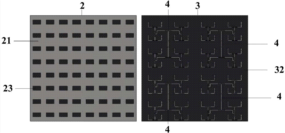
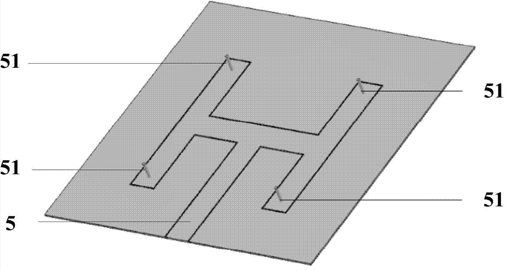
[0014] The cavity-backed slot antenna array provided by the present invention includes a metal back cavity 1, two dielectric substrates 2 and 3, a strip line feed network 4, an SIW feed network 5, dielectric resonators 6 and 7, and dielectric resonators 8 and 9.

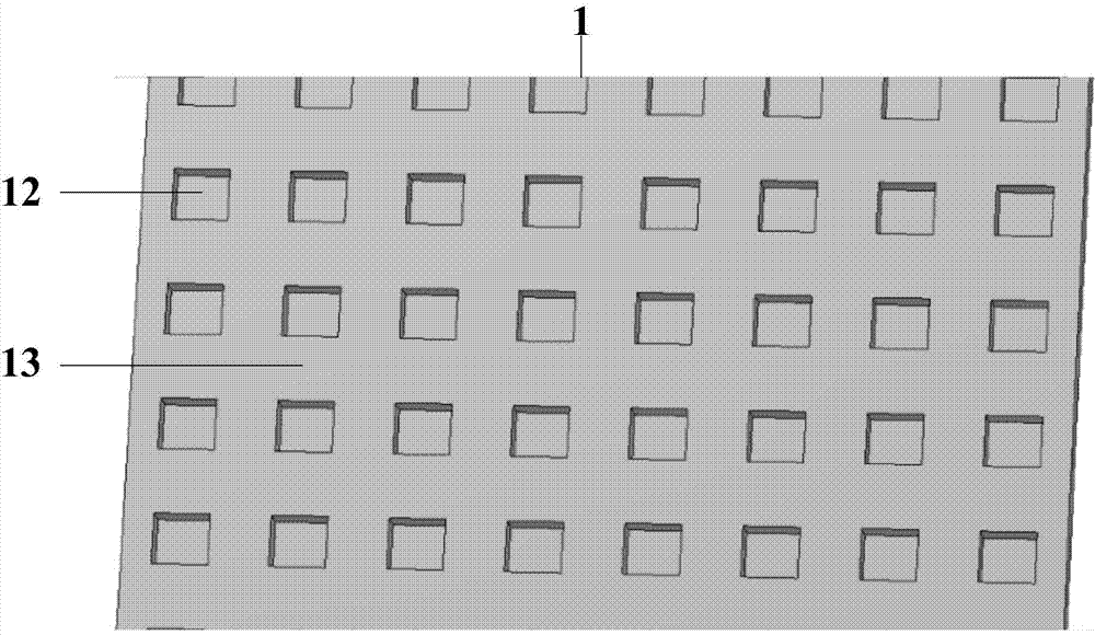
[0015] figure 1 It is a structural schematic diagram of the metal back cavity mentioned in the present invention. As shown in the figure, the metal back cavity 1 is a cuboid structure, and the upper surface 13 of the cuboid has more than one rectangular cross-section groove 12, the rectangular cross-section groove 12 does not penetrate the metal back cavity 1, the length of the rectangular cross-section groove 12, The width and depth are determined according to actual conditions, and the higher the frequency of the cavity-backed slot antenna array, the smaller the dimensions of the length, width and depth....


PUM


Abstract

The invention provides a back-cavity slot antenna array on the basis of SIW process and dielectric harmonic device structure. The back-cavity slot antenna array comprises a metal back cavity, two layers of dielectric substrates, an SIW feed network, a wired feed network and a plurality of dielectric harmonic device sets, the metal back cavity is of a cuboid structure, a plurality of rectangular section grooves which are identical and uniformly distributed in the surface of the metal back cavity, the SIW feed network is fixed on the lower surface of a cuboid, the dielectric substrates after being overlapped are fixed on one face, where the grooves are formed, of the metal back cavity, the wired feed network is sandwiched between the dielectric substrates and electrically connected with the SIW feed network through a coaxial probe, and each dielectric harmonic device set comprises two dielectric harmonic devices which are overlapped and fixed on the dielectric substrates. The back-cavity slot antenna array has the advantages of large bandwidth and high efficiency and can be widely applied in broadband radar systems.

Description

technical field [0001] The present invention relates to an antenna applied in the technical field of broadband radar system, more specifically a cavity-backed slot antenna array based on SIW (Substrate Integrated Waveguide, substrate integrated waveguide) technology and dielectric resonator structure. Background technique [0002] Slot antennas are often given priority when designing aircraft antennas due to their compact structure and easy conformability. A typical slot antenna is fed by a simple microstrip line, and a slot is opened on the metal bottom surface of the dielectric substrate to radiate electromagnetic energy into space. In practical applications, slot antennas often need to achieve unidirectional radiation. The usual solution is to add a metal cavity or reflective wall behind the slot. In 1963, Galejs first proposed a rectangular slot antenna with a back cavity, and carried out a detailed theoretical analysis of this cavity back slot antenna, and deduced the ...

Claims


Application Information

Patent Timeline
Patent Type & Authority Applications(China)
IPC IPC(8): H01Q1/38H01Q1/50H01Q13/18
Inventor 杨虎何艳金祖升卢俊麒宋崇硕吴雨晴徐延林林沂
Owner NAT UNIV OF DEFENSE TECH
Why Eureka
Try Eureka