Device for controlling input surge current of LED module

A LED module and inrush current technology, which is applied in lighting devices, lamp circuit layout, electric light sources, etc., can solve the problems of limited current limiting effect, large and slow inrush current, etc., achieve stable performance and prevent overcurrent big effect

Active Publication Date: 2015-07-01
OPPLE LIGHTING
View PDF7 Cites 7 Cited by
  • Summary
  • Abstract
  • Description
  • Claims
  • Application Information

AI Technical Summary

Problems solved by technology

However, since the resistance value of the NTC changes in a relatively slow process, the current limiting effect on poor contact or fast hot-swapping is relatively limited, and the NTC itself will generate heat, which will affect the temperature ch

Method used


Image

  • Device for controlling input surge current of LED module
  • Device for controlling input surge current of LED module
  • Device for controlling input surge current of LED module

Examples


Example Embodiment

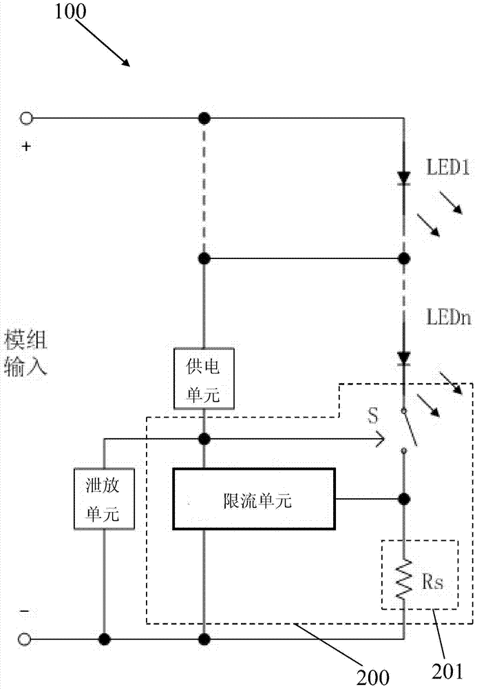
[0025] Please refer to image 3 As shown, an LED module input surge current control device 100 includes an LED module LED1-N, a power supply unit, and a control unit 200. The power supply unit supplies power to the control unit 200, and the control unit 200 is connected in series with the LED modules LED1-N. The control unit 200 includes a switching element S connected in series with the LED module LED1-N, a sampling circuit 201 connected to the switching element S, and a current limiting unit. The LED module LED1-N has a rated current, and the sampling circuit 201 samples the Current, when the current flowing through the LED module LED1-N is within the rated current range, the switching element S of the control unit 200 works in a saturated conduction state, when the current flowing through the LED module LED1-N is greater than the rated current range At this time, the current-limiting unit initiates current-limiting through the signal given by the sampling circuit 201, so tha...


PUM


Abstract

The invention discloses a device for controlling an input surge current of an LED module, and is used to control a current going through the LED module. The device comprises a power supply unit and a control unit; the power supply unit supplies power to the control unit; the control unit and the LED module are connected in series; and the control unit comprises a switch element which is connected in series with the LED module, a sampling circuit which is connected to the switch element, and also a current limiting unit; the LED module has a rated current; the sampling circuit samples the current going through the LED module; when the current flowing through the LED module is within a rated current range, the switch element of the control unit works in a saturated conduction state; when the current flowing through the LED module is greater than the rated current range, the current limiting unit starts limiting the current according to a signal sent by the sampling circuit, so that the switch element of the control unit works in a linear amplifying state; and accordingly, the current flowing through the LED module is controlled.

Description

【Technical field】 [0001] The invention relates to a control device, in particular to a control device for input surge current of an LED module. 【Background technique】 [0002] LED light source is more and more valued by the lighting industry due to its high luminous efficiency and long life. Different from traditional light sources, LED light sources require constant DC drive. Generally, a constant current drive power needs to be added between the input and the LED light source. Please refer to figure 1 As shown, the input voltage Vin can be an AC mains input or a DC input to provide power to the LED light source. The driving power supply is often a power conversion circuit, which can be a switching power supply or a linear constant current circuit, which is used to provide the DC signal required by the LED light source. The output terminal of the drive power supply is often connected with an output capacitor Co, which is mainly used to filter the output current ripple of ...

Claims


Application Information

Patent Timeline
IPC IPC(8): H05B37/02
Inventor 文威
Owner OPPLE LIGHTING
Why Eureka
Try Eureka