
Transmissions for Motor Vehicles

A technology of transmission and motor vehicle, applied in the direction of vehicle gearbox, transmission device, mechanical equipment, etc., can solve the problems of impossible transmission and complex transmission structure.

Active Publication Date: 2017-12-01
AUDI AG
View PDF1 Cites 0 Cited by
  • Summary
  • Abstract
  • Description
  • Claims
  • Application Information

AI Technical Summary

Problems solved by technology

The resulting transmission structure is relatively complex, and it is almost impossible to implement a transmission with more than two forward gears and possibly a reverse gear.

Method used


Image

  • Transmissions for Motor Vehicles
  • Transmissions for Motor Vehicles
  • Transmissions for Motor Vehicles

Examples


Embodiment Construction

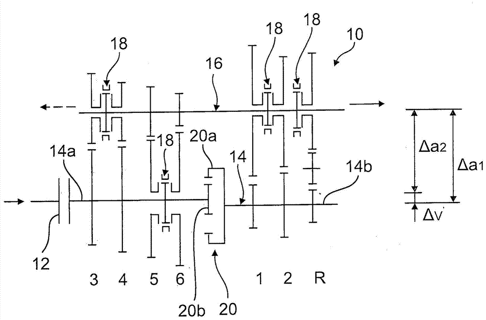
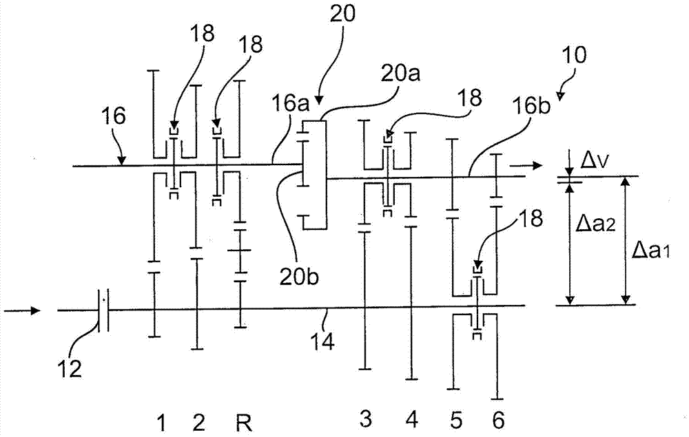
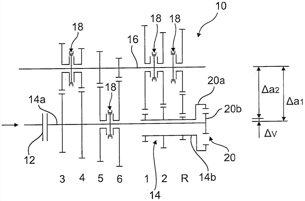
[0023] in figure 1 A transmission or shift transmission 10 for a motor vehicle is shown in the form of a block diagram without a transmission housing, which has an input shaft 14 and an output shaft 16 that can be connected to a driving device (not shown) via a disconnect clutch 12.

[0024] Arranged between the shafts 14 and 16 are gears of a gear set that mesh with each other. The gear set is used for six forward gears 1 to 6 and one reverse gear R. The floating gears of the gear sets 1 to 6 and the reverse gear R can be switched in a known manner by the synchronizing coupling device 18 that is only shown schematically, and can be connected to the corresponding fixed gears on the other shafts 14, 16 respectively. connection.

[0025] The two-piece input shaft 14 of the transmission 10 is engaged with each other through a ring gear stage 20, which has a ring gear 20a with a larger diameter and internal teeth and a cylindrical gear 20b meshing with the ring gear, wherein the suppor...


PUM


Abstract

The invention relates to a transmission for a motor vehicle, in particular a shifting transmission, having a plurality of forward gears and possibly a reverse gear, the transmission having at least an input shaft and an output shaft and possibly a countershaft, between which is arranged a The fixed gear of the range gear set and the floating gear that can be shifted by the synchromesh. The invention proposes that at least one of the shafts (14; 16; 46) be two-part and mounted in the transmission housing with mutually different rotational axes offset relative to one another by an axis offset (Δv), on the sub-shafts. A ring gear stage (20) is operatively arranged between (14a, 14b; 16a, 16b; 46a, 46b), the ring gear stage having an internally toothed ring gear (20a) and a belt meshing with the ring gear Externally toothed spur gear (20b), wherein the sub-shaft (14b; 16b; 46b) with a greater axial distance (a1) from the other shafts (16; 14; 44) supports in particular the lower forward gears (1, 1, 4) 2) and a possible reverse (R) gear.

Description

Technical field [0001] The invention relates to a transmission for a motor vehicle according to the preamble of claim 1, in particular a shift transmission. Background technique [0002] US 1 987 897 discloses a transmission with two forward gears in which ring gear stages are used to achieve different transmission ratios. In this case, either one of the gears on the countershaft is directly transmitted to the outer meshing ring gear, or the other gear on the countershaft is transmitted to a gear through an axially shifted shaft, and the gear passes all The shaft is driven to a cylindrical gear meshing with the internal teeth of the ring gear. The resulting transmission structure is relatively complicated, and it is almost impossible to achieve transmission with more than two forward gears and one reverse gear when necessary. Summary of the invention [0003] The object of the present invention is to provide a transmission of the type described, which can achieve a greater degre...

Claims


Application Information

Patent Timeline
Patent Type & Authority Patents(China)
IPC IPC(8): F16H3/08F16H3/04
CPCF16H3/093F16H2200/0052F16H2200/0017F16H1/10F16H3/44F16H57/0436F16H63/3425
Inventor C·迈克斯纳J·梅尔克
Owner AUDI AG
Learn More