A method and device for reducing power consumption of an ultrasound system

An ultrasonic system and low power consumption mode technology, applied in the structure of ultrasonic/sonic/infrasonic diagnostic equipment, control of ultrasonic/sonic/infrasonic equipment, ultrasonic/sonic/infrasonic diagnosis, etc., can solve the problem of large switching power supply interference, Reduce the performance of ultrasound images, reduce the signal-to-noise ratio of ultrasound, etc., to achieve the effect of reducing power consumption, power consumption reduction, and system power consumption

Active Publication Date: 2018-02-02
EDAN INSTR
View PDF6 Cites 0 Cited by
  • Summary
  • Abstract
  • Description
  • Claims
  • Application Information

AI Technical Summary

Problems solved by technology

However, in the prior art of ultrasound systems, most of the designs are designed with little consideration for low power consumption or no low power consumption design at all. There are a few methods by selecting low-power transmitting and receiving chips, or Configure the transmitting and receiving chip to low power consumption mode, but the above two methods have greatly reduced the performance of ultrasonic images, and some methods are to replace the ultrasonic power supply from linear to switching power supply, but the interference of switching power supply Large, it is easy to reduce the SNR of the ultrasonic signal. In general, the design of reducing power consumption in the prior art is at the expense of the SNR of the ultrasonic signal

Method used


Image

  • A method and device for reducing power consumption of an ultrasound system
  • A method and device for reducing power consumption of an ultrasound system
  • A method and device for reducing power consumption of an ultrasound system

Examples


Embodiment Construction

[0057] Embodiments of the present invention will be further described below in conjunction with the accompanying drawings.

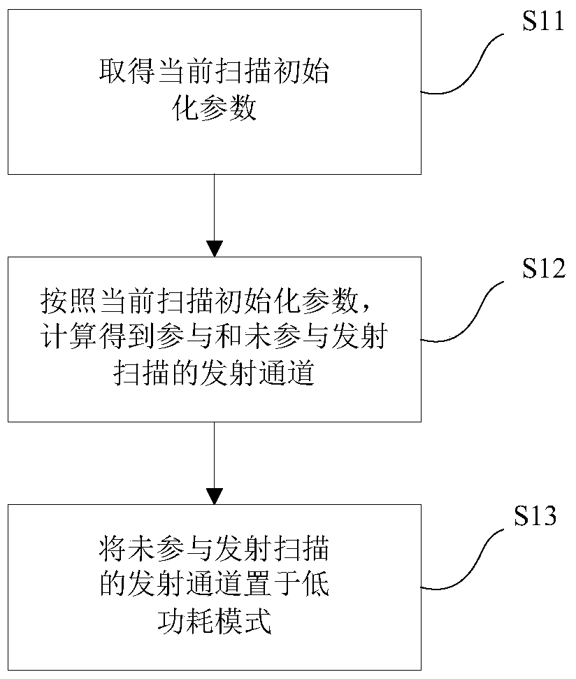
[0058] Such as figure 1 As shown, in the embodiment of the method and device for reducing power consumption of an ultrasound system of the present invention, the method includes the following steps:

[0059] Step S11 obtains the current scan initialization parameters: Generally speaking, a typical ultrasonic transmitting and receiving system includes a probe (transducer group), a transmitting chipset (transmitting channel), a receiving chipset (receiving channel), a beamformer, an image processing and main controller. The working process is as follows: the main controller sends the relevant parameters of transmission and reception in the scanning state, the scanning starts, the beamformer controls the transmission, the beamformer controls the reception, beamformation, and image processing. However, in this embodiment, it is necessary to distinguish the...


PUM


Abstract

A power consumption reducing method of an ultrasonic system, the method comprising the following steps: before an ultrasonic scan, acquiring an initial parameter of a current scan (S11); calculating, according to the acquired initial parameter of the current scan, to obtain an emission channel participating in a current scan emission and an emission channel not participating in the current scan emission (S12); and setting the emission channel not participating in the current scan emission to be a low-power-consumption mode (S13), setting the emission channel participating in the current scan emission to be an operation mode, and performing the current scan emission, the initial parameter of the current scan comprising a scan line number (A0), a scan emission aperture range (n0) and a scan receiving aperture range (n1), and the scan line number (A0) representing a center position of a scanning aperture. Also disclosed is a device using the above method. The power consumption reducing method and device of an ultrasonic system reduce system power consumption without affecting a signal-to-noise ratio.

Description

technical field [0001] The invention relates to the field of ultrasonic detection for medical treatment, more specifically, to a method and device for reducing power consumption of an ultrasonic system. Background technique [0002] Ultrasound systems generally use the number of channels to calculate system performance. The larger the number of channels, the higher the system performance, the better the image quality, and the higher the price, such as 32 channels, 64 channels, 128 channels, 256 channels, etc. However, when the general ultrasound system is working, it is rare for these channels to work at the same time. Taking a 128-channel ultrasound system as an example, in a certain scan, there are generally less than 64 transmitting channels and less than 96 receiving channels working at the same time. Traditional ultrasound systems generally keep 128 transmitting circuits and 128 receiving circuits in a waiting state, so that they can respond quickly when their work is ...

Claims


Application Information

Patent Timeline
Patent Type & Authority Patents(China)
IPC IPC(8): A61B8/00
CPCA61B8/44A61B8/54A61B8/00G06F1/32
Inventor 黎杰张仁富
Owner EDAN INSTR
Why Eureka
Try Eureka