Method and device for photonic band gap optical fiber backscattering distributed measurement

A backscattering and photonic bandgap technology, which is applied in testing optical fiber/optical waveguide equipment, testing optical performance, etc., can solve problems such as low spatial resolution and sensitivity, difficulty in suppressing polarization errors, and complex algorithms, so as to improve the scattering signal Intensity, extended measurement length, and improved signal-to-noise ratio

Active Publication Date: 2017-01-04
BEIHANG UNIV
View PDF8 Cites 6 Cited by
  • Summary
  • Abstract
  • Description
  • Claims
  • Application Information

AI Technical Summary

Problems solved by technology

OTDR locates and measures through the return time and light intensity of the light pulse, and the spatial resolution and sensitivity are low
The light source of the OFDR system is a linear sweep narrow-linewidth single longitudinal mode laser, which has high requirements on the light source. At the same time, it is difficult to suppress the polarization error of the system, and the demodulation requires Fourier transform, and the algorithm is complex.
Although OLCR has high measurement accuracy, the measurement length is short and the solution is complicated
Therefore, the existing optical fiber backscattering measurement cannot take into account the measurement accuracy and measurement length well, and it is necessary to provide a distributed measurement method and device for photonic bandgap fiber backscattering that can effectively solve the above problems

Method used


Image

  • Method and device for photonic band gap optical fiber backscattering distributed measurement
  • Method and device for photonic band gap optical fiber backscattering distributed measurement
  • Method and device for photonic band gap optical fiber backscattering distributed measurement

Examples


Embodiment Construction

[0022] The present invention will be further described in detail with reference to the accompanying drawings and embodiments.

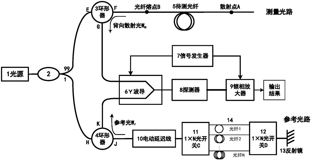
[0023] The invention is a photon bandgap optical fiber backscatter distributed measurement device, such as figure 1 As shown, it includes light source 1, 1:99 coupler 2, circulator 3 for measuring optical path, circulator 4 for reference optical path, optical fiber to be tested 5, Y waveguide 6, signal generator 7, detector 8, lock-in amplifier 9 , Electric delay line 10, 1×N optical switch C11, 1×N optical switch D12, optical fiber total reflection mirror 13 and ordinary single-mode optical fiber 1-N;

[0024] The maximum length of the change of the electric delay line 10 is △L, and the refractive index of common single-mode optical fiber 1, 2, ..., N is n, and the lengths are respectively

[0025] The wide-spectrum light output by light source 1 is divided into two beams of light with a light intensity ratio of 99:1 by a 1:99 coupler W m0 , W r...


PUM


Abstract

The invention discloses a device for photonic band gap optical fiber backscattering distributed measurement, which comprises a light source, a 1:99 coupler, a measurement optical path circulator, a reference optical path circulator, a to-be-measured optical fiber, a Y waveguide, a signal generator, a detector, a lock-in amplifier, an electric delay line, a 1*N-path optical switch C, a 1*N-path optical switch D, an optical fiber total mirror and common single-mode optical fibers 1 to N. Low-coherence optical interference and square wave and triangular wave-joint modulation and demodulation related detection technologies are used, and high-spatial resolution and high-sensitivity photonic band gap optical fiber backscattering distributed measurement is realized. As the 1:99 coupler and the circulators are used for adjusting the splitting ratio of the reference optical path to the measurement optical path, the scattering signal intensity is improved, and the signal-to-noise ratio of the system is improved. Through combination of the electric delay line and the optical switches, on the premise of not influencing the system resolution, the sensitivity and the signal-to-noise ratio, the measurement length of the device is expanded.

Description

technical field [0001] The invention belongs to the technical field of optical fiber characteristic parameter testing, and in particular relates to a high-precision measuring method and device for the backscattering distribution of a photonic bandgap optical fiber. Background technique [0002] Photonic bandgap fiber is a new type of microstructure fiber based on photonic bandgap effect, through SiO 2 The periodic arrangement of air holes and air holes forms a two-dimensional photonic crystal structure, which produces a photonic band gap effect, thereby limiting the propagation of light waves in the central air hole defect (core). Compared with traditional optical fibers, photonic bandgap optical fibers have many advantages, such as low sensitivity to environmental factors such as temperature, electromagnetic field, and space radiation, and insensitivity to bending. [0003] The backscattering of the optical fiber refers to the scattering in the scattered light within the n...

Claims


Application Information

Patent Timeline
Patent Type & Authority Applications(China)
IPC IPC(8): G01M11/02
CPCG01M11/31
Inventor 徐小斌闫明宋凝芳金靖滕飞蔡伟
Owner BEIHANG UNIV
Why Eureka
Try Eureka