Fluorescence Microscope and Fluorescence Microscope Method

Inactive Publication Date: 2008-09-04
OSAKA UNIV
View PDF2 Cites 10 Cited by
  • Summary
  • Abstract
  • Description
  • Claims
  • Application Information

AI Technical Summary

Benefits of technology

[0027]According to the present invention, it is possible to provide a fluorescence mi

Problems solved by technology

A spatial resolution of a general microscope is limited by diffraction limit.
Thus, existing microscopes have a problem that on

Method used


Image

  • Fluorescence Microscope and Fluorescence Microscope Method
  • Fluorescence Microscope and Fluorescence Microscope Method
  • Fluorescence Microscope and Fluorescence Microscope Method

Examples


first embodiment

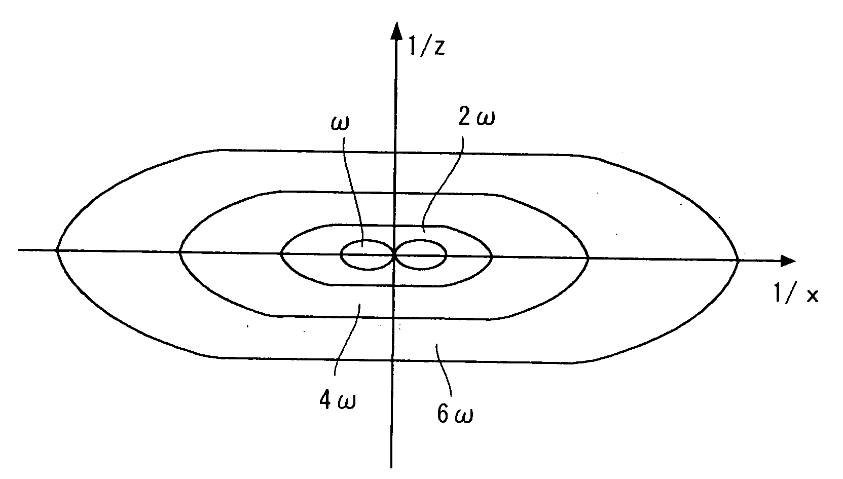
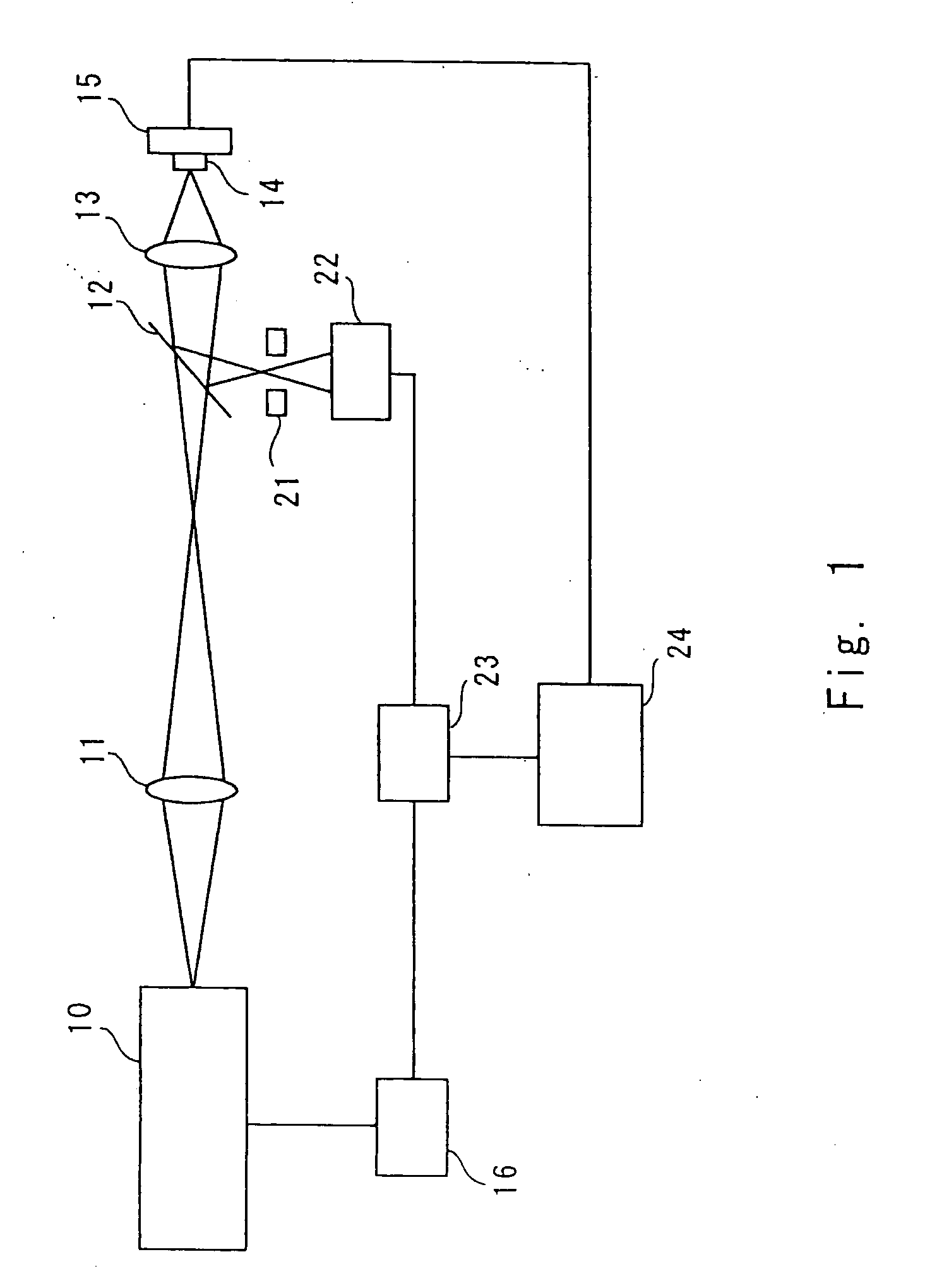
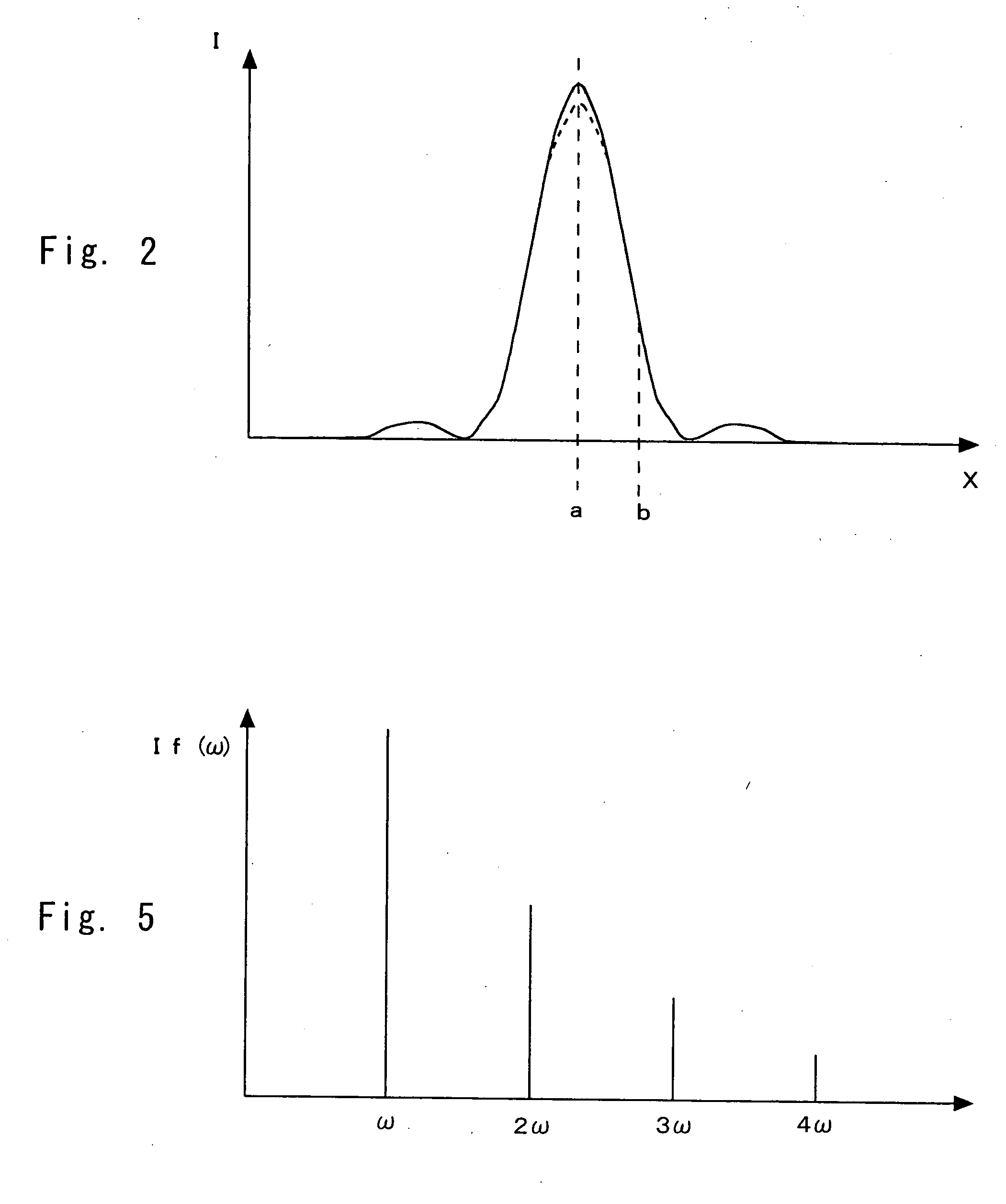
[0050]A fluorescence microscope according to a first embodiment of the present invention is a confocal microscope, in other words, a laser scanning type microscope. According to the present invention, spatial resolution is increased by utilizing saturation of fluorescence. That is, saturated components of fluorescence are observed to improve the spatial resolution. Referring to FIG. 1, the fluorescence microscope is described below. FIG. 1 schematically shows the structure of a fluorescence microscope of the present invention. Referring numeral 10 denotes a light source; 11, a lens; 12, a dichroic mirror; 13, a objective lens; 14, a sample; 15, a stage; 16, a modulator; 21, a pinhole; 22, a detector; 23, a lock-in amplifier; and 24, a processing apparatus.

[0051]The light source 10 is a laser light source for continuously emitting excitation light; for example, a continuous-wave Ar ion laser or a semiconductor ion laser having a wavelength in a visible range can be used. Here, the li...

second embodiment

[0083]A fluorescence microscope of this embodiment has the same structure as that of the first embodiment except that the light source 10 is a pulse laser light source. Target components are observed with two-photon excitation light in a similar fashion to the first embodiment to thereby increase spatial resolution. Incidentally, the same configuration as that of the first embodiment is omitted here.

[0084]As the light source 10, for example, a mode-locked titanium sapphire laser (wavelength of 750 nm, a pulse width of 100 fs, and repetition frequency of 80 MHz) is used. Further, the modulator 16 is used to perform intensity-modulation similar to the first embodiment. As the modulator, an electro-optical modulator (EO modulator) is used to perform modulation with 100 kHz. As described in the first embodiment, a repetition frequency of the pulse laser light is set much higher than the modulation frequency.

[0085]If two-photon excitation is used, photoexcitation itself is localized in a...

third embodiment

[0087]A fluorescence microscope of this embodiment applies laser beams of different intensities to observe a target site without modulating the laser light. The basic structure of the fluorescence microscope of this embodiment has the same structure as that of the fluorescence microscope of the first embodiment, so its description is omitted here. The fluorescence microscope of this embodiment is not provided with the modulator 16 in the fluorescence microscope of FIG. 1. Then, the sample 14 is irradiated with laser beams of different intensities from the light source 10. At this time, to irradiate the sample 14 with laser beams of different intensities, an output power of the light source 10 may be changed, or an intensity level of the laser light may be changed by using a filter such as an ND filter. Further, two or more light sources may be used. Further, these sources may be used in combination to change an intensity level of the laser light. Incidentally, laser beams of differe...


PUM


Abstract

To increase spatial resolution by observing a sample based on saturated fluorescence components. A fluorescence microscope according to the present invention includes: a laser light source 10 emitting laser light as excitation light; an objective lens 13 focusing the laser light and applying the focused laser light to a sample 14; a detector 22 detecting fluorescence generated in the sample 14 with the laser light; and a stage 15 scanning the sample 14 while moving the sample 14 relative to the laser light, wherein the laser light is applied to the sample with varying intensities such that saturation of fluorescence occurs at the maximum intensity of the laser light, and fluorescence is detected with the detector in accordance with intensity of the laser light, and the sample is observed based on the saturation components of fluorescence.

Description

TECHNICAL FIELD[0001]The present invention relates to a fluorescence microscope and a fluorescence microscopy method. In particular, the invention relates to a fluorescence microscope and a fluorescence microscopy method, which irradiate a sample with excitation light and detects fluorescence emitted by the sample to observe the sample.BACKGROUND ART[0002]Nowadays, fluorescence microscopes have been widely used as a tool efficient for medical and biological researches. In the fluorescence microscopes, excitation light from a light source is applied to a fluorescent material in a sample to make the fluorescent material emit fluorescence. Then, the fluorescence separated from the excitation light is detected to observe a fluorescence image of the sample. In the fluorescence microscopes, a fluorescent material is used as a fluorescence probe to label various cells or proteins and observe localization thereof.[0003]Further, a laser-scanning type fluorescence microscope has been used (fo...

Claims


Application Information

Patent Timeline
IPC IPC(8): G06F15/00
CPCG01N21/6408G01N21/6428G02B21/16G01N2201/0697G01N21/6458
Inventor FUJITA, KATSUMASAKAWATA, SATOSHINAKAMURA, NAOKONAKAMURA, OSAMUKOBAYASHI, MINORU
Owner OSAKA UNIV
Why Eureka
Try Eureka