
Quick reloading tool and small hole machine

A small hole machine and tooling technology, applied in the field of machine tools, can solve the problems of the lack of versatility of the small hole machine auxiliary workbench, low efficiency of repeated alignment and positioning, etc.

Inactive Publication Date: 2015-07-08
GOERTEK INC
View PDF6 Cites 0 Cited by
  • Summary
  • Abstract
  • Description
  • Claims
  • Application Information

AI Technical Summary

Problems solved by technology

[0004] The technical problem to be solved by the present invention is to provide a quick change tooling to solve the technical problem that the existing small hole machine auxiliary workbench lacks versatility and the efficiency of repeated alignment and positioning is low

Method used


Image

  • Quick reloading tool and small hole machine
  • Quick reloading tool and small hole machine
  • Quick reloading tool and small hole machine

Examples


Embodiment Construction

[0030] In order to make the object, technical solution and advantages of the present invention clearer, the present invention will be further described in detail below in conjunction with the accompanying drawings and embodiments. It should be understood that the specific embodiments described here are only used to explain the present invention, not to limit the present invention.

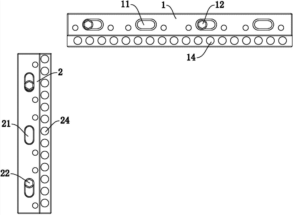
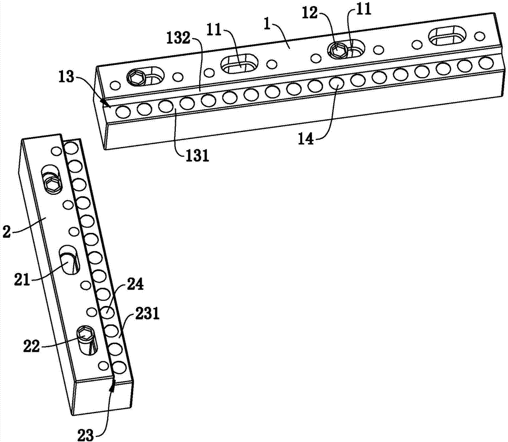
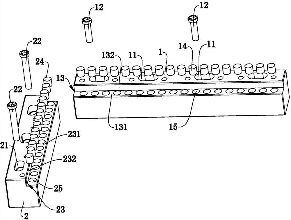
[0031] Such as Figure 1 to Figure 3 Commonly shown, a quick change tooling body includes two tooling bodies, the two tooling bodies are arranged at right angles and extend along the X direction and the Y direction respectively. For the convenience of description, one tooling body is defined as the X-direction tooling body 1, and the other A tooling body is defined as the tooling body 2 in the Y direction. In this embodiment, the length of the tooling body 1 in the X direction is greater than the length of the tooling body 2 in the Y direction. Of course, the lengths of the tooling body 1 in the X ...


PUM


Abstract

The invention discloses a quick reloading tool, belonging to the technical field of a machine tool. The quick reloading tool comprises two tool bodies, wherein two tool bodies are arranged in a right angle and respectively extend along an X-direction and a Y-direction; a right-angled nick consistent with the extending direction is formed in the internal side of each tool body; the right-angled nick comprises a horizontal plane for positioning the bottom surface of a plate material and a vertical plane for positioning the corresponding side of the plate material; magnets for fixing the plate material are formed in the horizontal plane of each tool body. The invention further discloses a small hole machine, which comprises a workbench; the quick reloading tool is arranged on the workbench. The quick reloading tool and the small hole machine are quick to clamp without repeatedly aligning and positioning and have strong practicability; meanwhile, the size of the plate material is not considered, thus the quick reloading tool and the small hole machine are convenient to assemble / disassemble and have wide application range; the quick reloading tool and the small hole machine are simple in operation and convenient to process, have lower cost, uniform standards and high processing efficiency.

Description

technical field [0001] The invention belongs to the technical field of machine tools, and in particular relates to a quick changing tool and also relates to a small hole machine. Background technique [0002] The current CNC small hole machine generally has two auxiliary worktables, one auxiliary workbench is fixed in the Y-axis direction of the small hole machine worktable, and the other auxiliary workbench is movable, and the sheet or template side is placed on the fixed On the auxiliary workbench, the other side is supported by a movable auxiliary workbench, and then the plate or formwork is fixed on the workbench by bolts with a pressure plate, and then the plate or formwork is aligned and positioned to complete the processing of the hole . [0003] When punching holes with the above-mentioned auxiliary workbench of the numerical control small hole machine, it is necessary to use a pressure plate to press the sheet or template every time, and each time punching needs to...

Claims


Application Information

Patent Timeline
IPC IPC(8): B23H9/14B23H11/00
CPCB23H9/14B23H11/003
Inventor 王磊谢兖选李照光
Owner GOERTEK INC
Learn More