
Clamp capable of ensuring perpendicularity between end surface of four-section installed and welded thin-wall cylindrical flange plate and axis

A thin-walled cylinder, axis vertical technology, applied in the direction of clamping, chuck, clamping device, etc., can solve the problem of inability to guarantee the tolerance value of the end face of the thin-walled cylinder flange and the axis perpendicularity of the four-stage welding, and improve the The effect of product qualification rate

Active Publication Date: 2015-07-08
HARBIN JIANCHENG GRP
View PDF7 Cites 4 Cited by
  • Summary
  • Abstract
  • Description
  • Claims
  • Application Information

AI Technical Summary

Problems solved by technology

[0003] The purpose of the present invention is to provide a fixture that can ensure the perpendicularity between the end face of the thin-walled cylindrical flange and the axis of the four-stage assembly welding, so as to solve the problem that the existing technology cannot guarantee the perpendicularity between the end face of the four-stage assembly and welding thin-walled cylindrical flange and the axis. difference in Questions within

Method used


Image

  • Clamp capable of ensuring perpendicularity between end surface of four-section installed and welded thin-wall cylindrical flange plate and axis
  • Clamp capable of ensuring perpendicularity between end surface of four-section installed and welded thin-wall cylindrical flange plate and axis
  • Clamp capable of ensuring perpendicularity between end surface of four-section installed and welded thin-wall cylindrical flange plate and axis

Examples


Embodiment Construction

[0020] The present invention will be further described in detail below in conjunction with the accompanying drawings.

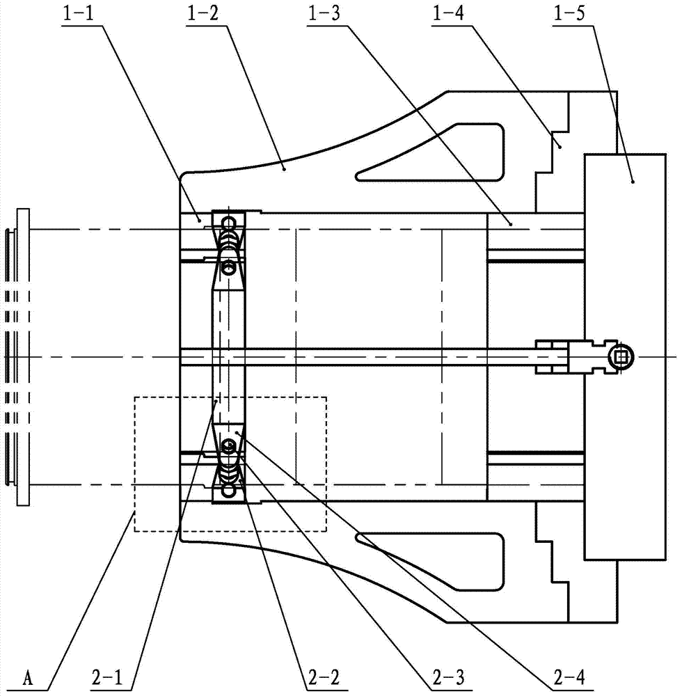
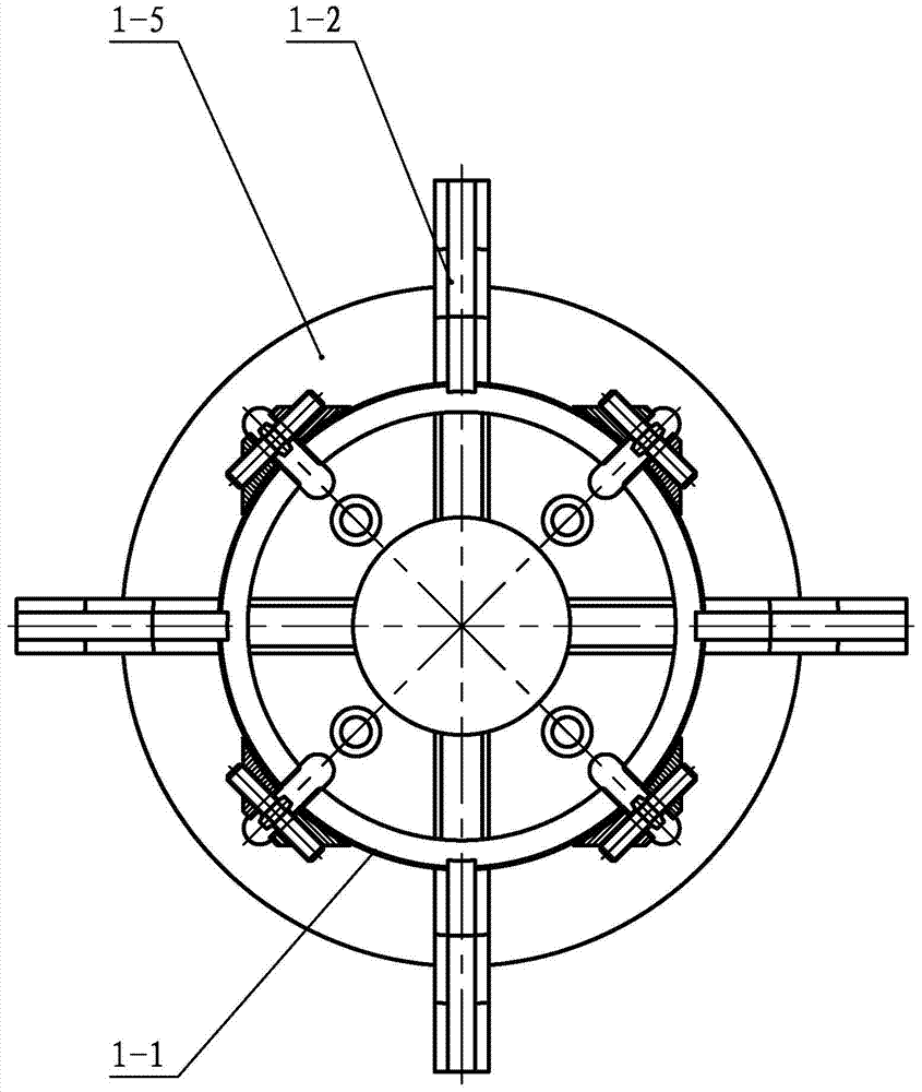
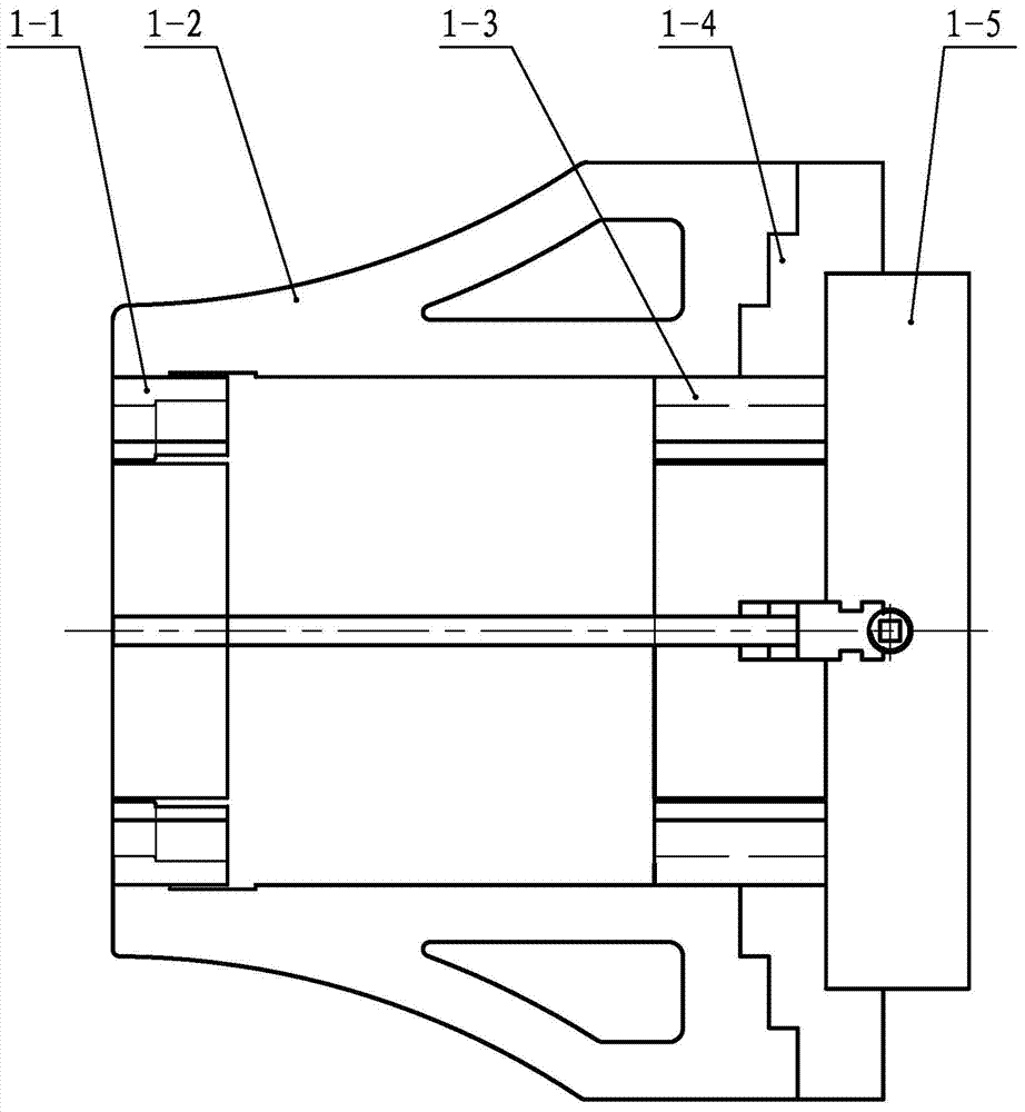
[0021] Such as Figure 1 to Figure 10 As shown, the fixture that can ensure the perpendicularity between the end face of the thin-walled cylindrical flange and the axis of the four-section assembly welding includes an arc-shaped long-arm combined card body assembly and a spring snap ring assembly; the arc-shaped long-arm combined card body assembly includes Four front-end arc-shaped plates 1-1, four extension arms 1-2 and four rear-end arc-shaped plates 1-3; the spring clasp assembly includes four arc-shaped spring steel strips 2-1 , four left-hand thread clamping seats 2-2, four left and right thread locking bolts 2-3 and four right-hand thread clamping seats 2-4; four extension arms 1-2 are symmetrically arranged in a cross shape, and the four front ends The arc-shaped plates 1-1 are symmetrically arranged in a cross shape and are arranged in the space sur...


PUM


Abstract

The invention discloses a clamp capable of ensuring perpendicularity between an end surface of a four-section installed and welded thin-wall cylindrical flange plate and an axis and relates to a clamp capable of ensuring perpendicularity between the end surface of the welded thin-wall cylindrical flange plate and the axis. The clamp is used for solving the problem that the tolerance value of the perpendicularity between the end surface of the four-section installed and welded thin-wall cylindrical flange plate and the axis is within FORMULA. Four lengthened arms are symmetrically arranged in a crossed manner, four front end circular-arc plates and four rear-end circular-arc plates are arranged in a space enclosed by the four lengthened arms; front and rear end circular-arc plates are welded at front end rear ends of long straight side surfaces of the lengthened arms respectively; the step end surfaces at the rear ends of the lengthened arms are matched and welded with the step end surface of a lathe chuck claw; the lathe chuck claw is connected with a threaded rod of the lathe chuck; left and right threaded clamping bases are welded at the two ends of a circular-arc-shaped spring steel belt, and the left and right threaded clamping bases are connected with left and right threaded locking bolts; spring chuck ring assemblies are arranged on four front-end circular-arc plates in a sleeving mode. The clamp can be used for ensuring the perpendicularity between the end surface of the four-section installed and welded thin-wall cylindrical flange plate and the axis.

Description

technical field [0001] The invention relates to a fixture capable of ensuring the perpendicularity between the end face of a thin-walled cylinder flange and an axis after welding, and belongs to the technical field of metal cutting and fixture design. Background technique [0002] For a four-section welded thin-walled cylinder with a flange on the end face (the four-section cylinder is welded together by three circular welds to form a four-section welded thin-walled cylinder, one end of the four-section welded thin-walled cylinder is connected to the French One end face of the flange plate is welded as a whole), after welding, the flange end needs to be processed such as grooving, and the shape tolerance requires that the perpendicularity tolerance of the flange end face relative to the axis is The axial length of the original fixture is only 200mm, and the non-welded end of the four-section welded thin-walled cylinder can only be clamped by a chuck. The two end faces afte...

Claims


Application Information

Patent Timeline
Patent Type & Authority Applications(China)
IPC IPC(8): B23Q3/00B23B31/10
CPCB23B31/10B23Q3/00B23Q2703/10
Inventor 许连辅许雁冰于晶谷彦军
Owner HARBIN JIANCHENG GRP
Learn More