Oil storage tank with double-layer structure

A double-layer structure and oil storage tank technology, applied in the field of storage, can solve the problems of different oil quality in each layer, no solution proposed, increase in oil product processing costs, etc., to avoid the impact of deterioration, quality impact, and separation layer effect

Active Publication Date: 2018-05-15
定州市东方石油设备有限公司
View PDF8 Cites 2 Cited by
  • Summary
  • Abstract
  • Description
  • Claims
  • Application Information

AI Technical Summary

Problems solved by technology

[0002] It is known that oil blending is to test the product characteristics of various petroleum fractions. According to product characteristics such as: density, cetane number, octane number, fraction temperature, viscosity, impurity content, etc., according to the above indicators, according to the national standard Blend oil products according to the national standard fuel oil at the lowest cost. Chemical additives (mainly liquid fuels) and various waste oils (waste engine oil, tire oil, plastic oil, etc.) need to be added to the national standard or It is non-standard blending, which can satisfy the use of imported cars, domestic cars, high-speed engines, low-speed engines, etc. Finally, the blended finished oil products are stored in oil storage tanks; however, during the storage of finished oil products, due to the addition of Due to different density or long-term storage, the upper, middle and lower layers of oil in the oil storage tank are prone to stratification, resulting in different oil quality in each layer, which greatly affects its sales.
The current practice is to achieve the required oil quality through compounding process, which not only complicates the process, but also greatly increases the processing cost of the oil
[0003] For the problems in related technologies, no effective solutions have been proposed yet

Method used


Image

  • Oil storage tank with double-layer structure
  • Oil storage tank with double-layer structure
  • Oil storage tank with double-layer structure

Examples


Embodiment Construction

[0024] The following will clearly and completely describe the technical solutions in the embodiments of the present invention with reference to the accompanying drawings in the embodiments of the present invention. Obviously, the described embodiments are only some, not all, embodiments of the present invention. All other embodiments obtained by persons of ordinary skill in the art based on the embodiments of the present invention belong to the protection scope of the present invention.

[0025] According to an embodiment of the present invention, an oil storage tank with a double-layer structure is provided.

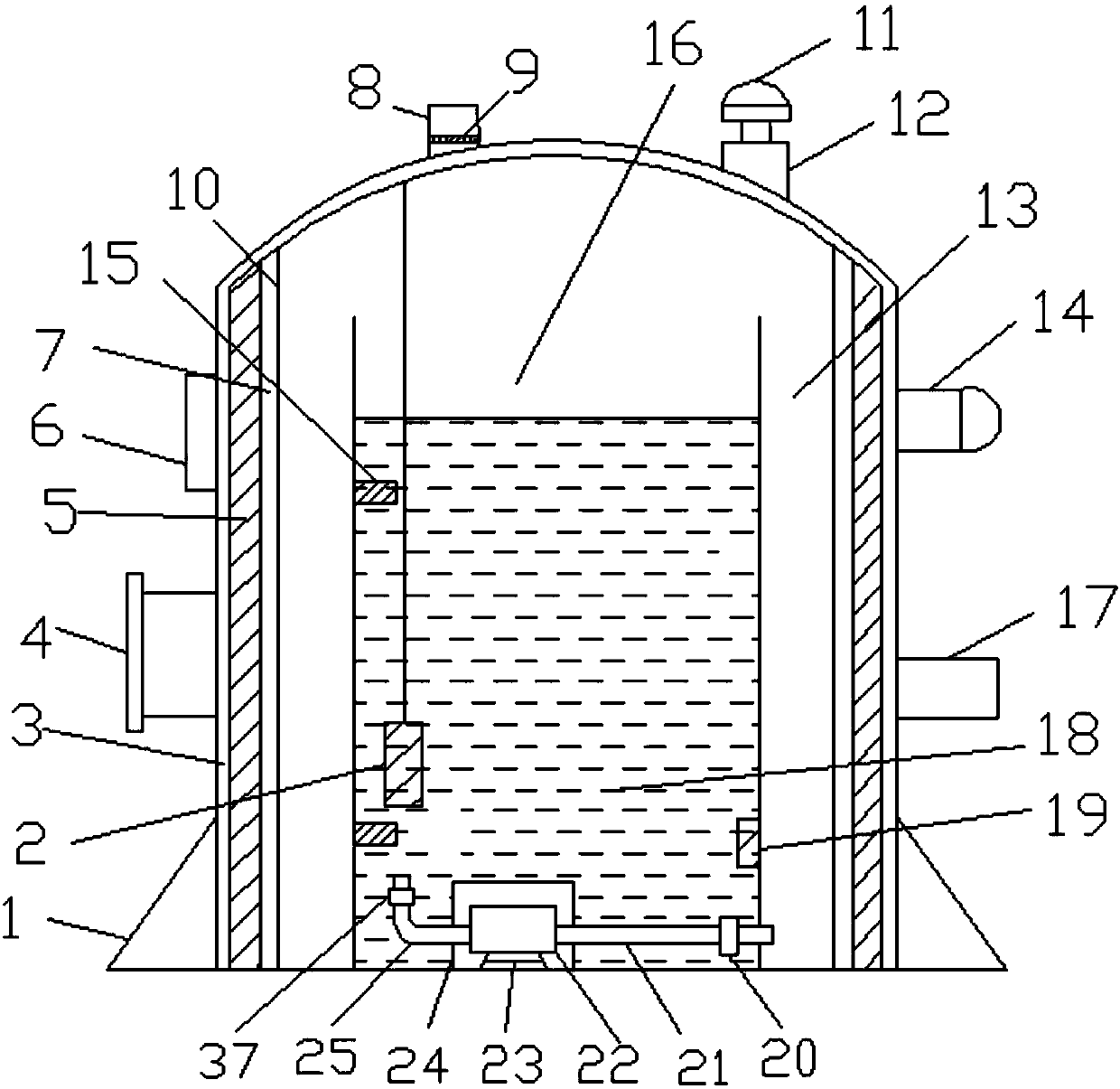
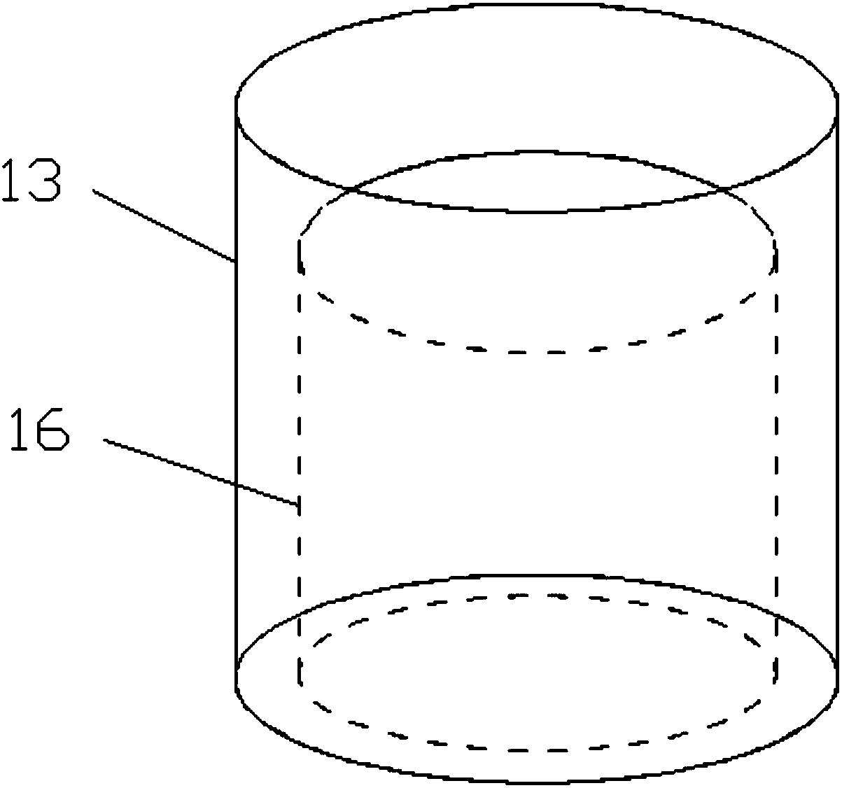
[0026] Such as Figure 1-3 As shown, an oil storage tank with a double-layer structure according to an embodiment of the present invention includes an oil storage tank body and a control module. hole 4, a display 6 is arranged above the manhole 4, an oil outlet pipe 17 is arranged on the other side of the bottom of the outer wall 3, a warning light 14 is arranged above...


PUM


Abstract

The invention discloses an oil storage tank with a double-layer structure. The oil storage tank comprises an oil storage tank body and a control module, the oil storage tank body comprises an outer wall, a manhole is formed in one side of the bottom of the outer wall, a displayer is arranged above the manhole, an oil outlet pipe is arranged on the other side of the bottom of the outer wall, a warning light is arranged on the upper portion of the oil outlet pipe, an oil inlet pipe is arranged on one side of the top of the outer wall, a filter screen is arranged at the bottom of the oil inlet pipe, a fire barrier is arranged on the other side of the top of the outer wall, a breather valve is arranged on the top of the fire barrier in a penetrating mode, an electromagnetic heating layer is arranged on the inner side of the outer wall, an insulating layer is arranged on the inner side of the electromagnetic heating layer, and the inner wall is arranged on the inner side of the insulating layer. The oil storage tank has the advantages that design is reasonable, the structure is simple, oil product stratification problem in the oil storage tank is effectively solved, and then the sales volume is effectively guaranteed; meanwhile, the processing charges of oil products are effectively lowered, and then the cost is effectively reduced.

Description

technical field [0001] The invention relates to the technical field of storage, in particular to an oil storage tank with a double-layer structure. Background technique [0002] It is known that oil blending is to test the product characteristics of various petroleum fractions. According to product characteristics such as: density, cetane number, octane number, fraction temperature, viscosity, impurity content, etc., according to the above indicators, according to the national standard Blend oil products according to the national standard fuel oil at the lowest cost. Chemical additives (mainly liquid fuels) and various waste oils (waste engine oil, tire oil, plastic oil, etc.) need to be added to the national standard or It is non-standard blending, which can satisfy the use of imported cars, domestic cars, high-speed engines, low-speed engines, etc. Finally, the blended finished oil products are stored in oil storage tanks; however, during the storage of finished oil produc...

Claims


Application Information

Patent Timeline
Patent Type & Authority Applications(China)
IPC IPC(8): B65D90/02B65D90/10B65D88/74B65D90/48G05D23/19G01D21/02
CPCB65D88/744B65D90/02B65D90/10B65D90/48G01D21/02G05D23/19
Inventor 何永萍
Owner 定州市东方石油设备有限公司
Why Eureka
Try Eureka