High turbidity water intake dredging system and method thereof

A high turbidity and dredging technology, which is applied in water supply equipment, drinking water equipment, soil movers/shovels, etc., can solve problems such as easy sedimentation, increased turbidity of raw water, and inconvenient dredging, etc., to ensure that Stabilize, simplify management, and reduce the effect of cement and sand

Active Publication Date: 2017-01-18
SHANGHAI MUNICIPAL ENG DESIGN INST GRP
View PDF8 Cites 0 Cited by
  • Summary
  • Abstract
  • Description
  • Claims
  • Application Information

AI Technical Summary

Problems solved by technology

The main disadvantages of the above-mentioned technology are: the bucket groove and the sand guide bottom sill are easy to deposit, and dredging is inconvenient, which may easily cause water intake facilities to increase water loss due to long-term deposition, increase raw water turbidity in dry seasons, and affect anaerobic fermentation of sludge Water quality and other issues affect the normal production of waterworks

Method used


Image

  • High turbidity water intake dredging system and method thereof
  • High turbidity water intake dredging system and method thereof
  • High turbidity water intake dredging system and method thereof

Examples


Embodiment 1

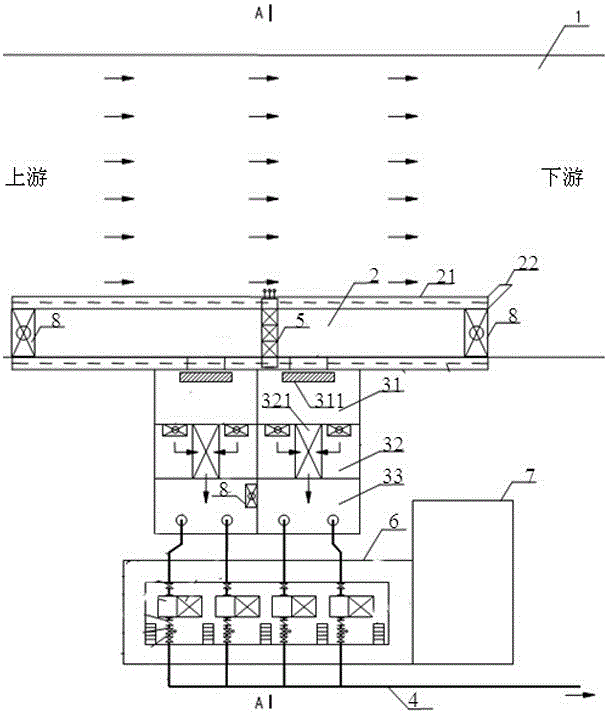
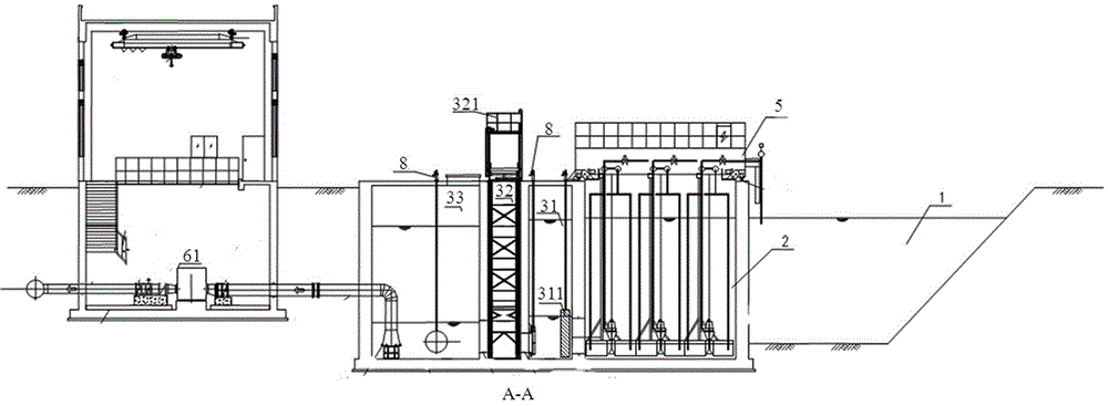
[0057] Such as figure 1 , 2 As shown, the present embodiment 1 is suitable for the water intake water body 1 is relatively wide, and the water intake water body management department allows the setting of the water intake rectification area 2 in the water body and allows the water intake pump room to be used under the situation of the water intake water body 1; In the water body 1, a water inlet and rectification area 2 is set near one side of the bank, and the middle part of the water inlet and rectification area 2 is connected with a water absorption well. The water pump 61 is located in the water intake pump room, the water pump room 6 and the power distribution room 7 are jointly built, and is connected with the water absorption well and the water purification plant through the pipeline system, and the water intake pump room 6 is also equipped with a motor, a lifting device, and a walkway , stairs and railings are connected to the suction well through the water inlet pipe...

Embodiment 2

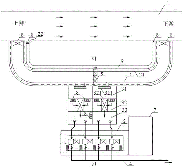
[0064] Such as image 3 , 4 As shown, this embodiment is suitable for the water intake water body 1 is relatively wide, and the water intake water body management department does not allow the water intake rectification area 2 to be set in the water body but allows the water intake pump room to be used under the situation of the water intake water body 1; in this embodiment, the described The water inlet rectification area 2 is arranged on the bank close to the water intake water body 1 side and is parallel to the water flow direction of the water intake water body 1; A partition gate 8 is set, and a mud discharge tank 9 is provided on one side of the water intake body 1, and a partition gate 8 is respectively provided at both ends of the mud discharge tank 9; the structure of the water intake well, the water intake pump room 6 and the power distribution room 7 is the same as in Embodiment 1 Same, no more details.

[0065] The form and operation mode of the flushing and suct...

Embodiment 3

[0067] Such as Figure 4 , 5 As shown, this embodiment is applicable to the water intake water body 1 is narrow, the water intake water body management department does not allow the water intake rectification area 2 to be set in the water body and the water intake pump room is not allowed to be used under the situation of the water intake water body 1; In this embodiment, a water inlet rectification area 2 is set on the bank near the water intake water body 1 side. One end of the mud discharge tank 9 is connected with the intake water body 1 and a partition gate 8 is set, and the other end of the water intake rectification area 2 is connected with the water absorption well; The front chamber 31 of the water suction well is transformed into a transitional form of the connecting area, specifically: partition walls 21 are arranged on both sides of the front chamber 31, and a grille 311 is arranged at the water inlet end and connected with the water inlet rectification area 2 at ...


PUM


Abstract

The invention discloses a water intaking and desilting system for high-turbidity water and a water intaking and desilting method thereof; the water intaking and desilting system for high-turbidity water comprises a water intaking body, an inflow commutating zone which is connected with the water intaking body and used for forming a low speed inflow channel for depositing sludge; an impulse suction dredge is arranged in the inflow commutating zone; a water absorbing well which is conncted with the inflow commutating zone and used for promoting the raw water; a pipeline system which is connected with the water absorbing well and used for transferring the water in the water absorbing well to a water treatment plant through a water pump. A water intaking and desilting method for high-turbidity water comprises the following steps: setting the inflow commutating zone, depositing the big particulate matter in the water of the zone; promoting the water after rectification; transferring the water after rectification. The system and the method have the advantages that the mud is discharged at fixed period for the low speed inflow channel which is easy to have deposition; the function of the raw water for washing deposition is combined for saving the water and energy, reducing inflow sediment, simplifying management and ensuring the stability of raw water quality.

Description

technical field [0001] The invention relates to the field of high turbidity water intake and cleaning, in particular to a high turbidity water intake and desilting system and a method thereof. Background technique [0002] The influent water of urban waterworks in my country contains a variety of organic and inorganic substances, most of which exist in the form of sedimentation. Usually, these substances are removed by sedimentation after entering the waterworks through water intake facilities. The water intake structures that use high-turbidity raw water often have low horizontal velocity in the water intake rectification area, and the undissolved particles in the raw water are easy to deposit and form silt, which increases the workload of the water intake structures. At the same time, the sediment due to Anoxic fermentation at the bottom of the water will also have a negative impact on the water quality of the water intake. This production problem has become a major produc...

Claims


Application Information

Patent Timeline
Patent Type & Authority Patents(China)
IPC IPC(8): E03B3/00E02F5/28
Inventor 许嘉炯王如华
Owner SHANGHAI MUNICIPAL ENG DESIGN INST GRP
Why Eureka
Try Eureka