LGP (Light Guide Plate), backlight module and display device

A technology of backlight module and light guide plate, which is applied in the field of backlight module, display device and light guide plate, can solve the problems of vibration friction between the light guide plate and optical film and poor white point, so as to reduce the bad white point and reduce the Vibration friction, the effect of simplifying assembly

Inactive Publication Date: 2015-07-08
HEFEI BOE OPTOELECTRONICS TECH +1
View PDF16 Cites 6 Cited by
  • Summary
  • Abstract
  • Description
  • Claims
  • Application Information

AI Technical Summary

Problems solved by technology

[0004] In order to overcome the problems of vibration friction and poor white spots between the light guide plate and the optical film, an embodiment of the present invention provides a light guide plate, a backlight module and a display device

Method used


Image

  • LGP (Light Guide Plate), backlight module and display device
  • LGP (Light Guide Plate), backlight module and display device
  • LGP (Light Guide Plate), backlight module and display device

Examples


Embodiment Construction

[0034] In order to make the object, technical solution and advantages of the present invention clearer, the implementation manner of the present invention will be further described in detail below in conjunction with the accompanying drawings.

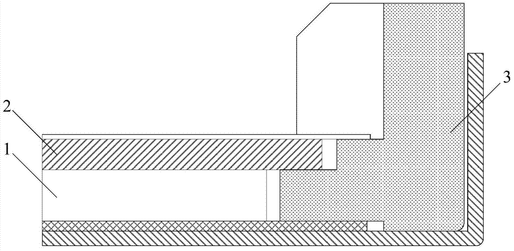
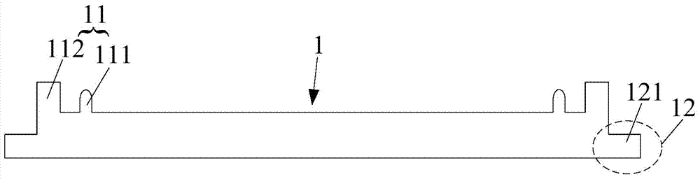
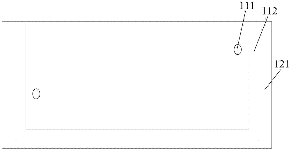
[0035] The light guide plate 1 provided by the embodiment of the present invention, such as figure 2 As shown, it includes: a diaphragm limiting part 11 and a fixing part 12 .

[0036] Wherein, the film limiting part 11 is arranged on the light emitting surface of the light guide plate 1, and is used for limiting the optical film.

[0037] The fixing part 12 is used for fixing the light guide plate 1 and the plastic frame.

[0038] The light guide plate provided by the embodiment of the present invention includes a film limiting part for limiting the optical film and a fixing part for fixing the light guide plate and the plastic frame, wherein the film limiting part is arranged on the light guide plate the light emitting surface. T...


PUM


Abstract

The invention discloses an LGP (Light Guide Plate), a backlight module and a display device, and relates to the field of a display technology. The LGP comprises a diaphragm limit part and a fixed part, wherein the diaphragm limit part is arranged on an emergent surface of the LGP and is used for limiting an optical diaphragm, and the fixed part is used for fixing the LGP and a plastic frame. Therefore, the LGP is capable of effectively solving the problems of vibration friction and bad white points between the LGP and the optical diaphragm.

Description

technical field [0001] The invention relates to the field of display technology, in particular to a light guide plate, a backlight module and a display device. Background technique [0002] Since a liquid crystal display panel is not a self-luminous display device, a backlight module is usually used as a backlight in an existing liquid crystal display device. The light guide plate (English: light guide plate; abbreviation: LGP) is an important part of the backlight module, which can convert the point light source or line light source provided by the backlight into a surface light source. [0003] The traditional light guide plate is usually a flat plate, and only exists in the backlight module as a pure optical component. The structure of the backlight module in the prior art is as follows figure 1 As shown, the optical film 2 and the light guide plate 1 are separately fixed in the backlight module, wherein the optical film 2 is limited by the stepped structure of the plas...

Claims


Application Information

Patent Timeline
IPC IPC(8): F21V8/00F21V17/10
CPCG02B6/0088G02B6/0055F21V17/10
Inventor 储汉奇蔡斯特朴辰武陈守年方明
Owner HEFEI BOE OPTOELECTRONICS TECH
Why Eureka
Try Eureka