Active false target jamming polarization discrimination method
A technology of polarization identification and false target, applied in the field of target identification and false target interference identification, it can solve the problems of decreased identification rate, sensitive signal-to-noise ratio, long processing time, etc., and achieve the effect of shortening the processing time.
- Summary
- Abstract
- Description
- Claims
- Application Information
AI Technical Summary
Problems solved by technology
Method used
Image

Examples
Embodiment Construction
[0023] The present invention will be further described below in conjunction with the accompanying drawings.
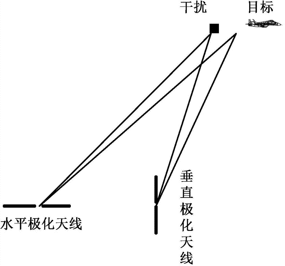
[0024] refer to figure 1 , the use scenarios of the present invention include: horizontally polarized antennas, vertically polarized antennas, targets and interference. The horizontally polarized antenna and the vertically polarized antenna are used to transmit electromagnetic wave signals to the area to be detected to detect the target, the target is used to scatter electromagnetic wave signals, and the jammer is used to receive the transmitted signals of the two antennas and forward them after delay processing to achieve the purpose of interference .
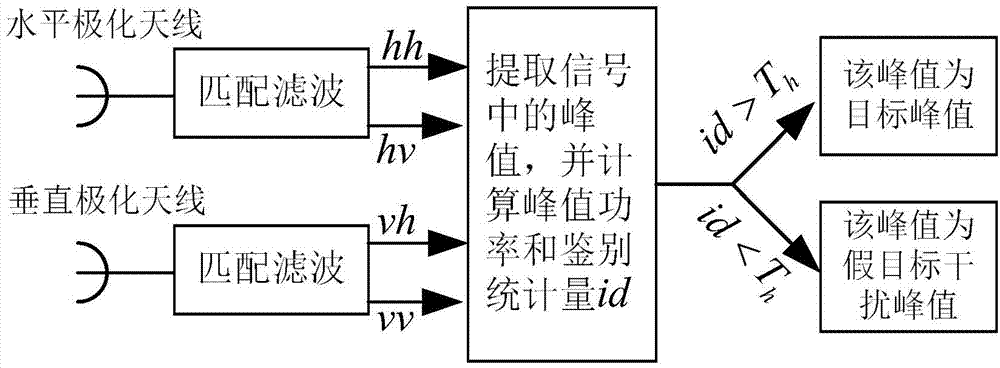
[0025] refer to figure 2 , in the above scenario, the specific implementation steps of the present invention for identifying active false target interference are as follows:
[0026] Step 1, transmitting electromagnetic wave signals.
[0027] The horizontally polarized antenna transmits electromagnetic wave signal...
PUM
 Abstract
Description
Claims
Application Information