Preparation method for back plate

A backplane and motherboard technology, applied in the field of communication, can solve problems such as insufficient accuracy, poor quality of backplane products, and inability to avoid leakage of etching solution or potion, so as to reduce damage and improve product quality.

Inactive Publication Date: 2015-07-08
HUAWEI TECH CO LTD
View PDF6 Cites 5 Cited by
  • Summary
  • Abstract
  • Description
  • Claims
  • Application Information

AI Technical Summary

Problems solved by technology

Wherein, the bond size c between the protective layer 07 and the adhesive layer 06 at the position of the window opening 071 of the protective layer 07 cannot be too small, so as to prevent the passage of the etching solution and the chemical solution when the protective layer 07 is etched and opened. Penetration into the crimping blind hole 05; at the same time, the size d of the protective layer 07 etching window 071 needs to consider the offset error during manual alignment, so the accuracy is not enough
[0006] The above preparation method is mostly used to prepare backplanes with a distance between the crimping holes of 1.9mm. It is getting smaller and smaller (for example, the minimum hole diameter of the crimping hole in the backplane commonly used in the industry is close to 0.40mm or even smaller, and the minimum distance between the crimping holes reaches 1.2mm or even smaller), the above preparation method A backplane with a smaller spacing between the crimping holes will not be able to avoid the leakage of etching solution or potion during the window opening process, which will cause damage to the crimping blind holes, resulting in poor product quality of the backplane Facilitates high-density placement of crimped blind vias in backplanes

Method used


Image

  • Preparation method for back plate
  • Preparation method for back plate

Examples


Embodiment Construction

[0029] The following will clearly and completely describe the technical solutions in the embodiments of the present invention with reference to the accompanying drawings in the embodiments of the present invention. Obviously, the described embodiments are only some, not all, embodiments of the present invention. Based on the embodiments of the present invention, all other embodiments obtained by persons of ordinary skill in the art without making creative efforts belong to the protection scope of the present invention.

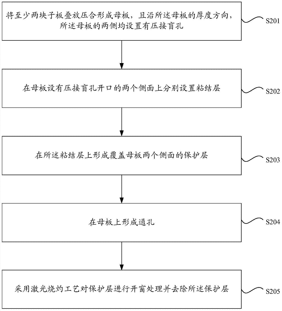
[0030] Please refer to figure 2 , the preparation method of the backplane provided in this embodiment includes:

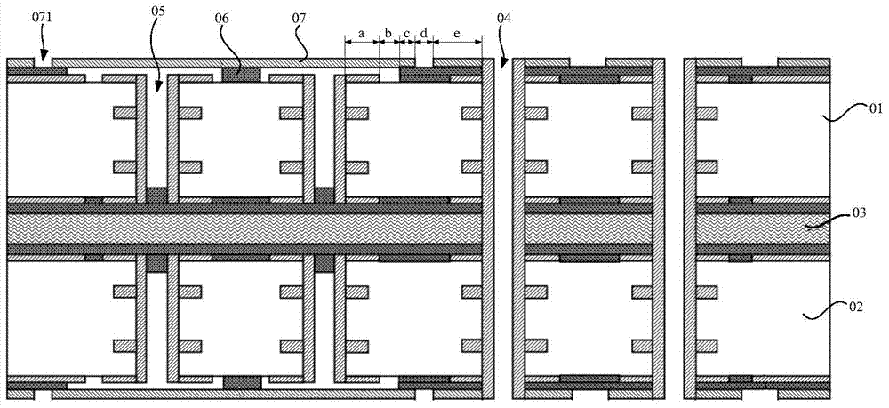
[0031] Step S201: stack and press at least two sub-boards to form a motherboard, and along the thickness direction of the motherboard, both sides of the motherboard are provided with crimping blind holes;

[0032] Step S202: setting adhesive layers on the two sides of the mother board provided with crimping blind hole openings;

[0033] Step S20...


PUM


Abstract

The invention relates to the technical field of communication, and discloses a preparation method for a back plate. The preparation method for the back plate comprises the steps that two or more daughter boards are pressed to form a mother board, and crimping blind holes are formed in the two sides of the mother board in the thickness direction of the mother board. Bonding layers are arranged on the two side faces, provided with openings of the crimping blind holes, of the mother board respectively. Protecting layers covering the two side faces of the mother board are formed in the bonding layers. Through holes are formed in the mother board. Windowing treatment is conducted on the protecting layers by laser burning technology and the protecting layers are removed. According to the preparation method for the back plate, when removing the protecting layers is needed, the windowing treatment is conducted on the protecting layers through the laser burning technology, etching liquid and medical liquid are not utilized, and thereby considering the windowing position, the bonding size between the protecting layers and the bonding layers and the size and standard of windowing and the like are not needed, so that the preparation method for the back plate is convenient to achieve the high-density arrangement of the crimping blind holes in the back plate conveniently, damage on the crimping blind holes during preparing of the back plate can be reduced, and the product quality of the back plate is improved.

Description

technical field [0001] The invention relates to the technical field of communications, in particular to a method for preparing a backplane. Background technique [0002] In the field of communication technology, with the rapid development of network products, network products have higher and higher requirements on the channel capacity of the backplane. [0003] At present, in order to increase the channel capacity of the backplane, those skilled in the art form a high-density double-sided crimped backplane by adopting the process of setting crimping blind holes on both sides of the backplane when preparing the backplane, and setting pressure-bonded holes on both sides of the backplane at the same time. Connect blind holes, and then crimp connectors can be crimped on both sides of the backplane, thereby increasing the channel capacity of the backplane. [0004] Such as figure 1 As shown, the above-mentioned backboard includes a first sub-board 01, a second sub-board 02, and...

Claims


Application Information

Patent Timeline
Patent Type & Authority Applications(China)
IPC IPC(8): H01R43/00
CPCH01R43/00H01R43/20
Inventor 杨永星刘山当高峰
Owner HUAWEI TECH CO LTD
Why Eureka
Try Eureka