Sealed stator

A technology of sealing stators and stators, which is applied in the manufacture of stator/rotor bodies, winding insulation shapes/styles/structures, magnetic circuit shapes/styles/structures, etc., can solve problems such as long flow paths and shortened sealing

Active Publication Date: 2018-01-02
SUNONWEALTH ELECTRIC MACHINE IND
View PDF5 Cites 0 Cited by
  • Summary
  • Abstract
  • Description
  • Claims
  • Application Information

AI Technical Summary

Problems solved by technology

[0005] The main purpose of the present invention is to solve the above-mentioned problem that the flow path of the sealant in the mold is too long in the existing sealant stator, so as to provide a sealant stator structure that can effectively shorten the flow path of the sealant in the mold

Method used


Image

  • Sealed stator
  • Sealed stator
  • Sealed stator

Examples


Embodiment Construction

[0039] In order to make the above-mentioned and other objects, features and advantages of the present invention more comprehensible, the preferred embodiments of the present invention are specifically cited below, together with the accompanying drawings, as follows:

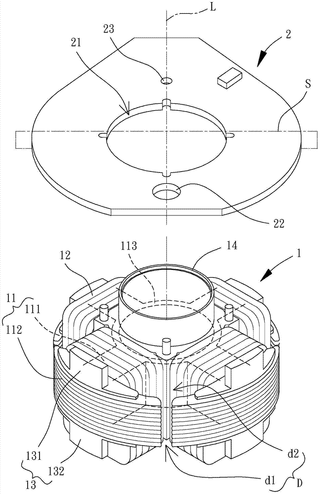
[0040] Please refer to image 3 and 4 As shown, the sealant stator of the present invention at least includes a stator assembly 1 , a circuit board 2 and sealant 3 . The circuit board 2 is disposed at one end of the stator set 1 ; the sealant 3 covers the stator set 1 and the circuit board 2 .

[0041] The above-mentioned stator assembly 1 at least includes an iron core 11 and a coil 12 . Please refer to Figure 5 As shown, the iron core 11 is provided with several pole arms 111, and the several pole arms 111 are arranged radially with a distance from each other. One end of the several pole arms 111 is respectively provided with a magnetic conduction part 112, any of which There is a first gap d1 between the ...


PUM


Abstract

A sealant stator, which includes a stator group, a circuit board and sealant. The stator set includes an iron core and a coil, the coil is wound and combined with the iron core; the circuit board is electrically connected to the coil, and the circuit board is provided with glue injection holes and ventilation holes; the sealant covers the stator set and the circuit board; wherein the glue injection hole of the circuit board is used to shorten the flow path of the sealant when it is injected into a mold.

Description

technical field [0001] The invention relates to a sealed stator, in particular to a structure in which the stator can be integrally covered with glue. Background technique [0002] Please refer to figure 1 As shown, the existing rubber-sealed stator 9 has a magnetic pole piece group 91, and a coil group 92 is wound around the magnetic pole piece group 91. The coil group 92 is electrically connected to a circuit board 93 with a vent hole 931, and is covered with epoxy resin 94 and other sealing glue covers the magnetic pole piece group 91, the coil group 92 and the circuit board 93 to form a closed and integrated stator structure, so that the existing glue-sealed stator 9 has a waterproof and moisture-proof effect. An embodiment similar to the above-mentioned sealed stator 9 is disclosed in the Chinese invention patent No. 201010503545.6 "Fan Motor". [0003] Also, please refer to figure 2 As shown, in the process of coating the epoxy resin 94 in the above-mentioned exist...

Claims


Application Information

Patent Timeline
Patent Type & Authority Patents(China)
IPC IPC(8): H02K1/12H02K11/30H02K3/34H02K15/02
Inventor 谢坤利杨净越
Owner SUNONWEALTH ELECTRIC MACHINE IND
Why Eureka
Try Eureka