
Motor control method, motor module using motor control method and radiating device

A technology of motor control and motor controller, which is applied in the direction of excitation or armature current control, etc., can solve the problems of excessive running noise, inability to rotate at low speed, etc., and achieve the effect of reducing startup noise

Active Publication Date: 2015-07-08
QISDA SUZHOU +1
View PDF8 Cites 2 Cited by
  • Summary
  • Abstract
  • Description
  • Claims
  • Application Information

AI Technical Summary

Problems solved by technology

Generally speaking, the fan is usually started at a high speed, although this can quickly cool down, but it causes the problem of excessive operating noise
[0003] In terms of fan operation modes, it can generally be divided into DC voltage mode (DC mode) and pulse width modulation mode (PWM mode). The common disadvantage of both is that the speed cannot be reduced to a low speed.

Method used


Image

  • Motor control method, motor module using motor control method and radiating device
  • Motor control method, motor module using motor control method and radiating device
  • Motor control method, motor module using motor control method and radiating device

Examples


Embodiment Construction

[0047] In order to have a further understanding of the purpose, structure, features, and functions of the present invention, the following detailed descriptions are provided in conjunction with the embodiments.

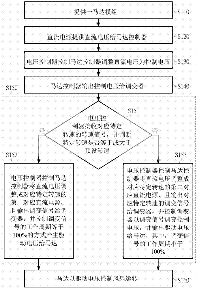
[0048] figure 2 A flowchart of a motor control method according to an embodiment of the invention is shown.

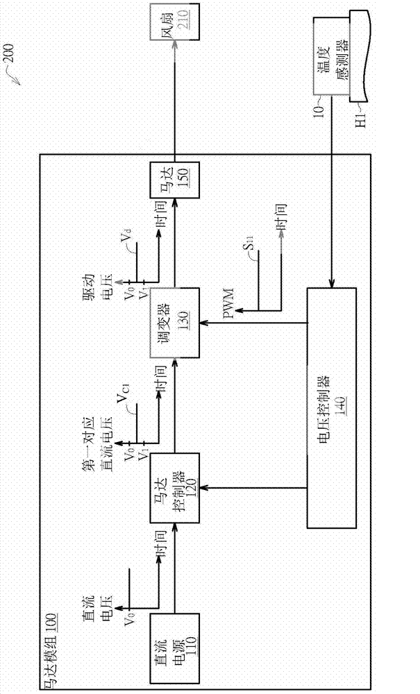
[0049] In step S110, provide as image 3 Motor module shown. image 3 A functional block diagram of a heat dissipation device according to an embodiment of the invention is shown. The heat dissipation device 200 includes a motor module 100 and a fan 210. The motor module 100 includes a DC power supply 110, a motor controller 120, a modulator 130, a voltage controller 140, and a motor 150. The motor module 100 is used to control the operation of the fan 210 to reduce the temperature of the hot spot H1. The motor 150 is, for example, a DC motor.

[0050] In step S120, the DC power supply 110 provides a DC voltage V 0 Give the motor controller 120. In one embodimen...


PUM


Abstract

The invention provides a motor control method, a motor module using the motor control method and a radiating device. The motor control method includes the following steps: providing the motor module; adjusting the control voltage into the driving voltage through a modulator, wherein the step includes the processes that a voltage controller judges whether a specific rotating speed is larger than a preset rotating speed or not; when the preset rotating speed is equal to or larger than the preset rotating speed, the direct-current voltage is adjusted into a first corresponding direct-current voltage corresponding to the special rotating speed through a motor controller and is provided for a motor; when the special rotating speed is smaller than the preset rotating speed, the direct-current voltage is adjusted through the motor controller into a second corresponding direct-current voltage corresponding to the special rotating speed, an adjusting signal corresponding to the special rotating speed is output to the modulator, and the modulator adjusts the second corresponding direct-current voltage with the adjusting signal and outputs the driving voltage to the motor; the working period of the adjusting signal is smaller than 100%. By means of the adjusting design of the embodiment, the motor module can run at a low speed, and the starting noise of a fan is accordingly reduced.

Description

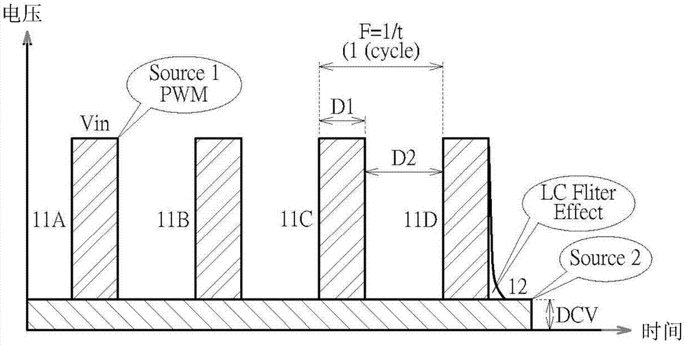
Technical field [0001] The present invention relates to a motor control method, a motor module and a heat dissipation device using the same, and more particularly to a motor control method using a modulated signal, and a motor module and heat dissipation device using the same. Background technique [0002] In order to solve the heat dissipation problem, traditional technologies use fans to reduce the hot spot temperature. Generally speaking, fans usually start at a high speed. Although this can quickly cool down, it causes excessive operating noise. [0003] In terms of fan operation mode, it can be generally divided into DC mode and PWM mode. The common disadvantage of both is that the rotation speed cannot be reduced to a low speed. Therefore, a common method between the two modes has been created. [0004] For example, Taiwan Patent Publication No. TW201134083A1 discloses a speed regulation method for DC motors with dual power supplies. In this patent, such as figure 1 As shown...

Claims


Application Information

Patent Timeline
Patent Type & Authority Applications(China)
IPC IPC(8): H02P7/06
Inventor 郭文豪王博文黄崇荣田政璋
Owner QISDA SUZHOU
Learn More