Driving oil way of variable valve mechanism with VVT and VVL system

A technology of valve mechanism and driving oil circuit, which is applied in the direction of machines/engines, mechanical equipment, engine components, etc., to achieve the effects of shortening the filling amount of engine oil, simplifying the structure of oil circuit, and improving control speed and precision

Active Publication Date: 2013-06-12
CHERY AUTOMOBILE CO LTD
View PDF0 Cites 0 Cited by
  • Summary
  • Abstract
  • Description
  • Claims
  • Application Information

AI Technical Summary

Problems solved by technology

However, the two-stage variable valve lift mechanism under this form has not yet been mass-produced.

Method used


Image

  • Driving oil way of variable valve mechanism with VVT and VVL system

Examples


Embodiment Construction

[0030] The present invention will be described in detail below according to the accompanying drawings, which is a preferred embodiment among various implementations of the present invention.

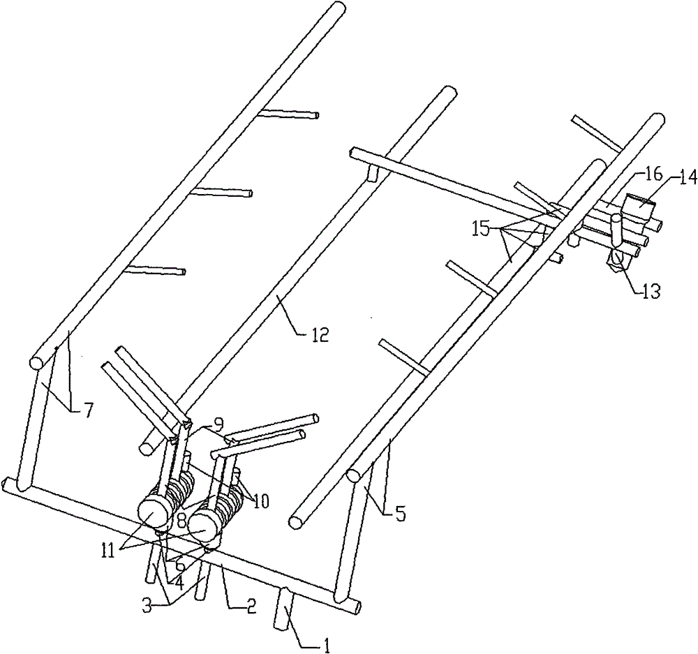
[0031] Such as figure 1 , as shown in Figure 2, a drive oil circuit of a variable valve mechanism with both VVT and VVL technologies, the engine oil flows through the main oil passage 1 of the cylinder block to the main oil passage 2 of the cylinder head, and then flows into the intake camshaft respectively Neck oil supply passage 5, VVT oil passage inlet 4, exhaust camshaft journal oil supply passage 7. The engine oil in the intake camshaft journal oil supply passage 5 further flows into the exhaust hydraulic lash adjuster oil passage 12 to control the oil passage inlet 13 by the VVL system. The VVT ​​oil passage inlet 4 is arranged in the middle of the cylinder head, and a check valve 6 is installed in the VVT ​​oil passage, and its installation position is between the VVT ​​oil passa...


PUM


Abstract

The invention relates to a driving oil way of a variable valve mechanism with VVT and VVL system. The driving oil way comprises a VVT oil way, a cam shaft journal lubricating oil way, a hydraulic clearance adjuster oil way, a VVL system control oil way and one-way valves (6), wherein the VVT oil way is arranged in the middle of a cylinder cover; the cam shaft journal lubricating oil way is arranged on the two sides of the cylinder cover; the VVL system control oil way is integrated in the hydraulic clearance adjuster oil way; and a plurality of one-way valves (6) are arranged between a VVT oil way inlet (4) on the oil way of the cylinder cover and an engine oil control valve OCV (11) of the VVT system, and opened when the VVT system works normally and closed when an engine is stopped or idles.

Description

technical field [0001] The invention belongs to the technical field of engines, and in particular relates to a driving oil circuit of a variable valve mechanism having both VVT and VVL technologies. Background technique [0002] With the development of the automobile industry, the requirements for engine performance, fuel consumption and emissions are getting higher and higher, and variable valve technology has become one of Peugeot's key technologies to measure engine performance. The variable valve mechanism has changed the fixed valve timing and valve lift in the traditional engine, and provides the best valve timing and valve lift within the range of engine operating conditions, which better solves the problem of high speed and The contradiction between power performance and economy under low speed, large load and small load, and improved exhaust emission at the same time. [0003] The electromagnetically driven valve mechanism can control the valve lift and valve timin...

Claims


Application Information

Patent Timeline
Patent Type & Authority Patents(China)
IPC IPC(8): F01L9/02F02F1/20F02F1/24F01M9/10F01L1/24F01L9/10
Inventor 曹健夏德刚苏晓寒
Owner CHERY AUTOMOBILE CO LTD
Why Eureka
Try Eureka