Analog-to-digital converter and image sensor

An analog-to-digital conversion and counter technology, which is applied in analog-to-digital converters, time-to-digital converters, and analog-to-digital conversions, can solve problems such as increased power consumption and reduced A/D conversion performance

Inactive Publication Date: 2015-07-08
KK TOSHIBA
View PDF5 Cites 16 Cited by
  • Summary
  • Abstract
  • Description
  • Claims
  • Application Information

AI Technical Summary

Problems solved by technology

[0004] However, the TDC requires a high-speed clock signal, and if the high-speed clock signal is also supplied to the TDC during rough A/D conversion using a ramp signal, power consumption will increase.
[0005] In addition, in t

Method used


Image

  • Analog-to-digital converter and image sensor
  • Analog-to-digital converter and image sensor
  • Analog-to-digital converter and image sensor

Examples


no. 1 Embodiment approach

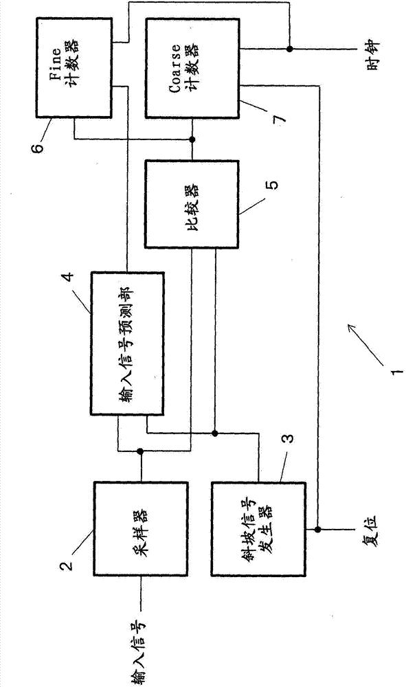
[0029] figure 1 It is a block diagram showing a schematic configuration of the analog-to-digital converter 1 of the first embodiment. figure 1 The analog-to-digital converter 1 includes a sampler 2 , a ramp signal generator 3 , an input signal predictor 4 , a comparator 5 , a Fine (fine) counter 6 , and a coarse (coarse) counter 7 .

[0030] The sampler 2 holds sampled signals obtained by sampling the input signal at predetermined time intervals. The ramp signal generator 3 generates a ramp signal. A ramp signal refers to a signal whose signal level monotonically increases or monotonically decreases as time passes. That is, the ramp signal refers to a signal in which the voltage increases by Δv while a certain time Δt passes, or a signal in which the voltage decreases by Δv while Δt passes.

[0031] The ramp signal generator 3 can be formed by an integrator. In an integrator, Δt is one clock period, and Δv means the integrated voltage within one clock period. The ramp sig...

no. 2 Embodiment approach

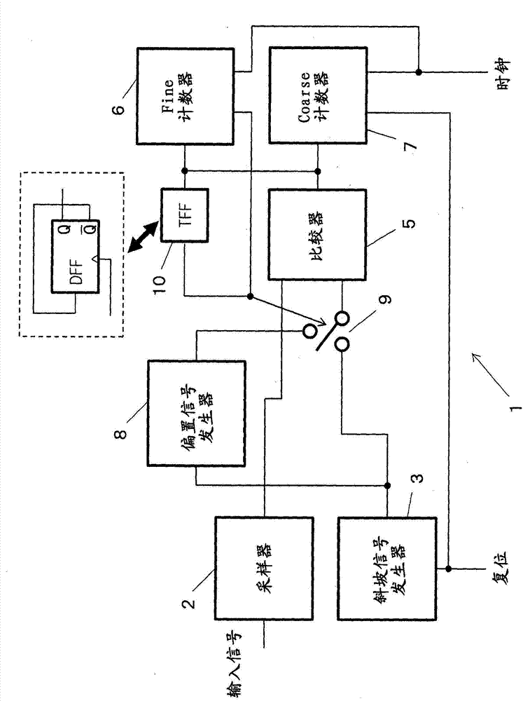
[0067] if figure 2 , Figure 5 If the signal switching unit 9 switches between two input signals, the input signal level of the comparator 5 may fluctuate greatly for a while. Image 6 is an equivalent circuit diagram of a signal path connecting the signal switching unit 9 and the comparator 5, Figure 7 is the signal waveform diagram of the signal path.

[0068] A wiring resistance R and an input capacitance C of the comparator 5 exist on the signal path connecting the signal switching unit 9 and the comparator 5 . When the input capacitance C of the comparator 5 is large, a sudden change in the signal level of the signal path occurs due to a settling operation of charge charged in the input capacitance C. That is, when the signal switching unit 9 switches the signal and as a result, the signal level of the signal supplied to the comparator 5 changes abruptly, the Image 6 The output voltage of the low-pass filter constituted by the wiring resistance R of the comparator ...

no. 3 Embodiment approach

[0082] In the third embodiment described below, two types of comparators 5 are provided.

[0083] Figure 10 is a block diagram showing a schematic configuration of the analog-to-digital converter 1 of the third embodiment, Figure 11 yes Figure 10 The signal waveform diagram of the analog-to-digital converter 1. Figure 10 The analog-to-digital converter 1 replaces the figure 1 The signal switching unit 9 and the comparator 5 include a first comparison unit 5a and a second comparison unit 5b. Other structures and figure 1 common.

[0084] The first comparison unit 5a compares the signal levels of the bias signal and the sampling signal, and outputs a signal indicating the comparison result. The second comparison unit 5b compares the signal levels of the ramp signal and the sampling signal, and outputs a signal indicating the comparison result.

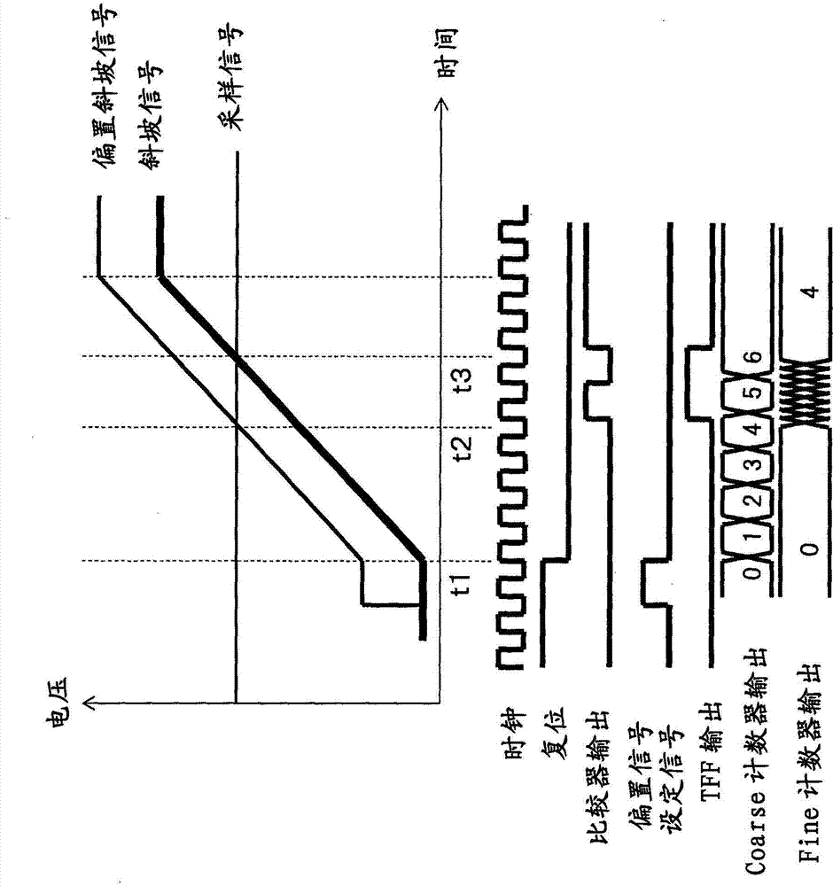
[0085] When the reset is removed and the ramp signal generator 3 starts to generate the ramp signal ( Figure 11 At time t1...


PUM


Abstract

An analog-to-digital converter has a sampler to hold a sampled signal, an input signal predictor to generate a prediction signal at predetermined timing before a signal level of a ramp signal that monotonically increases or monotonically decreases with time crosses a signal level of the sampled signal, a comparator to compare signal levels of the ramp signal and the sampled signal to output a comparison signal showing whether the signal level of the ramp signal is larger than the signal lever of the sampled signal, a first counter to perform a count operation in synchronism with a first clock signal within a period from start of a comparison operation by the comparator to generation of the prediction signal, and a second counter to perform a count operation in synchronism with a second clock signal.

Description

[0001] This application claims the priority of Japanese Patent Application No. 2014-1481 filed on January 8, 2014, and uses the entire content of the above-mentioned Japanese Patent Application in this application. technical field [0002] Embodiments of the present invention relate to an integrating analog-to-digital converter and an image sensor including the analog-to-digital converter. Background technique [0003] An integrating analog-to-digital converter (ADC: Analog-to-Digital Converter) using a time-to-digital converter (TDC: Time-to-Digital Converter) has been proposed. In such an integrating ADC, in addition to rough A / D conversion using a ramp signal, fine A / D conversion using a TDC is performed to improve the resolution of the A / D conversion , and realize its high speed. [0004] However, the TDC requires a high-speed clock signal, and if the high-speed clock signal is also supplied to the TDC while performing rough A / D conversion using a ramp signal, power con...

Claims


Application Information

Patent Timeline
IPC IPC(8): H03M1/12
CPCH04N5/3742H03M1/34H04N5/37455G04F10/005H03M1/002H03M1/14H03M1/56H04N25/75H04N25/767H04N25/772
Inventor 古田雅则白石圭篠塚康大
Owner KK TOSHIBA
Why Eureka
Try Eureka