Video defogging method and system based on FPGA

A video and video image technology, applied in the field of FPGA-based video dehazing methods and systems, can solve the problems of slow algorithm speed and large amount of calculation, and achieve the effect of delaying image time, satisfying real-time processing, and improving image quality.

Inactive Publication Date: 2015-07-08
SHENZHEN GENIUSUN TECH
View PDF3 Cites 2 Cited by
  • Summary
  • Abstract
  • Description
  • Claims
  • Application Information

AI Technical Summary

Problems solved by technology

[0003] The technical problem to be solved by the present invention is to propose an FPGA-based video defogging method and system to solve the problems that the existing algorithm is slow, has a large amount of calculation, and cannot be implemented on hardware

Method used


Image

  • Video defogging method and system based on FPGA
  • Video defogging method and system based on FPGA
  • Video defogging method and system based on FPGA

Examples


Embodiment Construction

[0037] In order to make the object, technical solution and advantages of the present invention clearer, the present invention will be further described in detail below in conjunction with the accompanying drawings and embodiments.

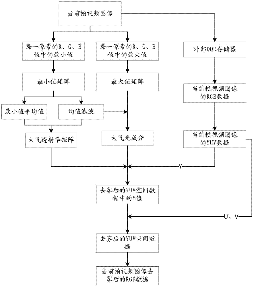
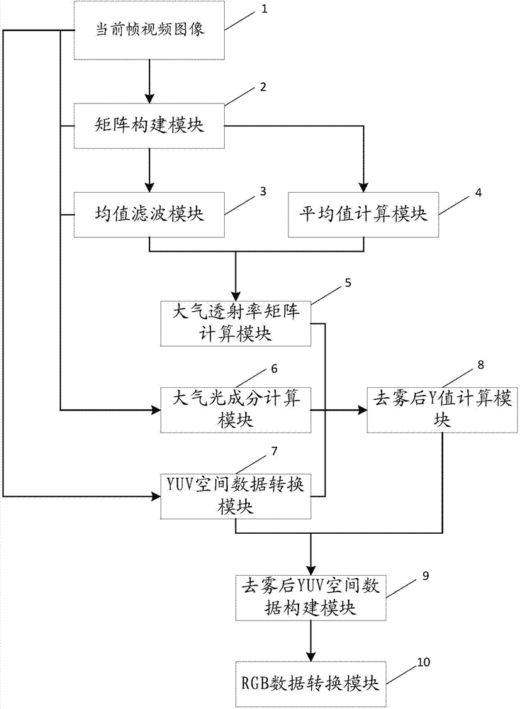
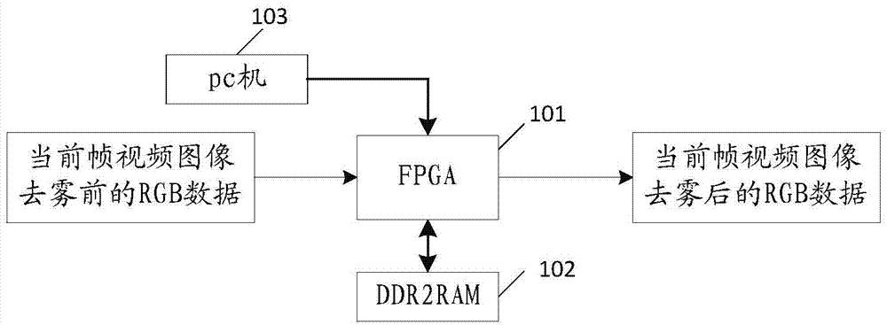
[0038] The present invention proposes to defog video through FPGA. Such as figure 1 As shown, the method specifically includes the following steps:

[0039] Step S1: Receive and store the current frame video image M(x), and at the same time, detect the maximum and minimum values ​​of the R, G, and B values ​​of each pixel in the current frame video image to obtain the maximum value matrix Max(x) and Minimum value matrix Min(x). For example, if the R, G, and B values ​​of a certain pixel are 223, 114, and 51 respectively, then the maximum value of the pixel is 223, and the minimum value is 51. The maximum value of each pixel constitutes a maximum value matrix Max(x), and the minimum value of each pixel constitutes a minimum value matrix Min(x). ...


PUM


Abstract

The invention relates to a video defogging method based on an FPGA. With the FPGA as a processing body, through detecting the maximum value and the minimum value of R, G and B values of each pixel in a current video image frame, a maximum value matrix and a minimum value matrix are obtained, the average value of all the minimum values in the minimum value matrix is calculated, and average filtering is performed on the minimum value matrix; according to an obtained average filtering matrix and the obtained average value, an atmospheric transmission ratio matrix is calculated; according to the maximum value matrix, the average filtering matrix and the current video image frame, the light component of atmosphere is calculated; when a next video image frame is received, RGB data of the current video image frame are read and converted into YUV spatial data; according to the atmospheric transmission ratio matrix, the light component of the atmosphere and a Y value in the YUV spatial data, a Y value in the defogged YUV spatial data is calculated, wherein the Y value and a U value and a V value in the YUV spatial data are combined to form the defogged YUV spatial data; the defogged YUV spatial data are converted into RGB data, and the RGB data after defogging the current video image frame are obtained.

Description

technical field [0001] The invention relates to the technical field of video image processing, in particular to an FPGA-based video defogging method and system. Background technique [0002] For videos shot under foggy or hazy weather conditions, due to the absorption and scattering of light by suspended particles in the atmosphere, the image quality is degraded and blurred, which reduces the visibility of the video and affects the follow-up Image processing is interfering. Existing dehazing algorithms are slow, computationally intensive, and cannot be implemented on hardware. Contents of the invention [0003] The technical problem to be solved by the present invention is to propose an FPGA-based video defogging method and system, so as to solve the problems that the existing algorithm is slow, has a large amount of calculation, and cannot be implemented on hardware. The present invention is achieved like this: [0004] A method for defogging video based on FPGA, said ...

Claims


Application Information

Patent Timeline
Patent Type & Authority Applications(China)
IPC IPC(8): H04N5/21G06T5/00
Inventor 欧阳平李跃勋
Owner SHENZHEN GENIUSUN TECH
Why Eureka
Try Eureka