Eureka AIR delivers breakthrough ideas for toughest innovation challenges, trusted by R&D personnel around the world.

Intelligent LED drive control circuit

A LED drive and control circuit technology, which is applied to the layout of electric lamp circuits, electric light sources, lighting devices, etc., can solve the problems of unable to adjust the output current and fixed output current, and achieve stable and reliable working performance, small size, and low cost. Effect

Inactive Publication Date: 2015-07-08
绍兴光大芯业微电子有限公司
View PDF7 Cites 2 Cited by
  • Summary
  • Abstract
  • Description
  • Claims
  • Application Information

AI Technical Summary

Problems solved by technology

Although the current LED drive power supply has achieved constant current output, the disadvantage is that the output current is fixed and the output current cannot be adjusted.

Method used


Image

  • Intelligent LED drive control circuit
  • Intelligent LED drive control circuit

Examples


Embodiment 1

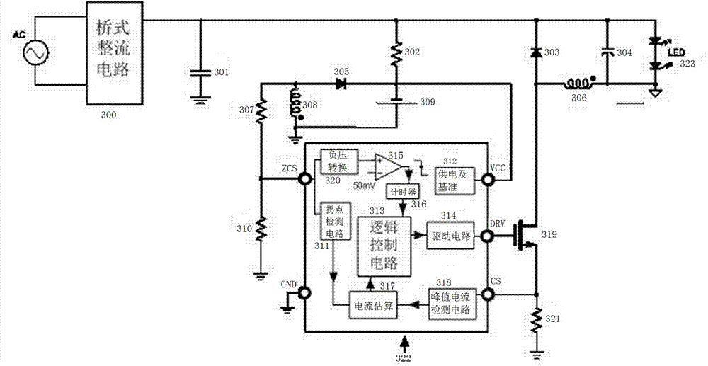
[0015] Such as figure 1 An intelligent LED drive control circuit is shown, which includes a bridge rectifier circuit 300 and an LED drive control circuit 322. The bridge rectifier circuit 300 is connected in parallel with a high-voltage filter capacitor 301, a first resistor 302, and an LED drive circuit 323, wherein the The first resistor 302 is connected in series with the second resistor 307, the second resistor 307 is grounded through the third resistor 310, the second resistor 307 and the third resistor 310 are connected to the LED drive control circuit 322, and the LED drive The control circuit 322 is connected to the gate of the power transistor 319 , and the source of the power transistor 319 is grounded through the fourth resistor 321 . The bridge rectifier circuit 300 is connected in parallel with the energy storage capacitor 304 .

[0016] The LED drive control circuit 322 includes a peak current detection circuit 318, a current estimation circuit 317, a logic cont...


PUM


Abstract

The invention discloses an intelligent LED drive control circuit. The intelligent LED drive control circuit comprises a bridge rectifier circuit and an LED drive control circuit body. The bridge rectifier circuit is connected with a high-voltage filter capacitor, a first resistor and the LED drive control circuit body in parallel. The first resistor is connected with a second resistor in series, the second resistor is connected to the ground through a third resistor, the second resistor and the third resistor are connected with the LED drive control circuit body, the LED drive control circuit body is connected with a power tube grid electrode, and a power tube source electrode is connected to the ground through a fourth resistor. According to the intelligent LED drive control circuit, the cost of the overall scheme is low, the size is small, the structure is simple and practical, the working performance is stable and reliable, and the application range is wide.

Description

technical field [0001] The invention relates to an intelligent LED dimming circuit, in particular to the technical field of light-emitting diode LED driving power supply, and specifically refers to an LED driving control circuit and its driving circuit structure that detects a mains switch to realize different output currents. Background technique [0002] In recent years, LED lighting has been widely used due to its advantages of high efficiency, energy saving, environmental protection and long life. In different usage occasions, the requirements for the brightness of LED lamps are also different. Although the current LED drive power supply has achieved constant current output, the disadvantage is that the output current is fixed and the output current cannot be adjusted. Contents of the invention [0003] The object of the present invention is to provide an intelligent LED drive control circuit, which has low overall cost, small volume, simple and practical structure, s...

Claims


Application Information

Patent Timeline
Patent Type & Authority Applications(China)
IPC IPC(8): H05B37/02
Inventor 孙菊根田剑彪孙文浩
Owner 绍兴光大芯业微电子有限公司
Why Eureka
Eureka Blog
Learn More