led drive control circuit

A technology for driving control circuits and control loops, which can be used in the layout of electric lamp circuits, electric light sources, lighting devices, etc., and can solve the problem of low reliability, inability to withstand large fluctuations in input and output voltages, and obstacles to mass production of LED lighting with linear drive methods and security applications to achieve the effect of improving the input response speed

Active Publication Date: 2018-01-26
SHANGHAI BRIGHT POWER SEMICONDUCTOR CO LTD
View PDF3 Cites 0 Cited by
  • Summary
  • Abstract
  • Description
  • Claims
  • Application Information

AI Technical Summary

Problems solved by technology

However, the current linear drive method always has low reliability, requires high matching of input voltage and output lamp beads, and cannot withstand large fluctuations in input and output voltages, which hinders the linear drive method from being used in mass production and safety applications of LED lighting. middle

Method used


Image

  • led drive control circuit

Examples


Embodiment Construction

[0013] The specific embodiments of the present invention will be further described in detail below with reference to the accompanying drawings.

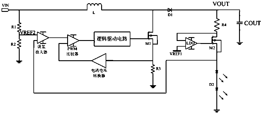
[0014] The LED drive control circuit of the present invention includes a DC input terminal, a DC output terminal, an output voltage feedback terminal, a control loop that controls the duty cycle of the power tube switch according to the output voltage feedback terminal, and a power tube connected to the control loop;

[0015] It also includes a first reference voltage VREF, LDO, a sampling resistor R4, and a regulator tube M2. The sampling resistor is connected between the DC output terminal and the drain of the regulator tube. The source of the regulator tube is connected to the load LED. The control terminal of the regulator tube Connected to the LDO output terminal, the two input terminals of the LDO are respectively connected to the common terminal of the regulator tube and the sampling resistor and the first reference voltage; the com...


PUM


Abstract

The LED drive control circuit includes a DC input terminal, a DC output terminal, an output voltage feedback terminal, a control loop and a power tube connected to the control loop; it also includes a first reference voltage, a linear voltage regulator, a sampling resistor and an adjustment tube, The sampling resistor is connected between the DC output terminal and the drain of the adjustment tube, the source of the adjustment tube is connected to the load LED, the control end of the adjustment tube is connected to the output end of the linear regulator, and the two The input terminal is respectively connected to the common terminal of the adjusting tube and the sampling resistor and the first reference voltage; the second reference voltage is a voltage dividing resistor string connected between the DC input terminal and the ground. The present invention realizes the on-demand supply of transmission energy by controlling the on and off of the charging energy path of the input to the output capacitor, and realizes the direct sampling of the input DC voltage by feeding back the DC input to the error amplifier, thereby improving the input response speed.

Description

Technical field [0001] The invention belongs to the field of integrated circuit design, and relates to a switching power supply, particularly an LED drive control circuit. Background technique [0002] With the development of high-voltage LED lamp beads and the increasingly stringent requirements for cost and volume of LED driving power supplies, low-cost high-voltage constant-current linear driving methods have achieved certain technological updates and applications in the past few years. However, the current linear driving method always has low reliability, high matching of input voltage and output lamp beads, and the inability to withstand large fluctuations in input and output voltage, which prevents the linear driving method from being applied to mass production and safety applications of LED lighting. in. Summary of the invention [0003] In order to overcome the shortcomings of the existing LED driving chip adopting linear regulator to control the voltage, the present inve...

Claims


Application Information

Patent Timeline
Patent Type & Authority Patents(China)
IPC IPC(8): H05B37/02
Inventor 高继赵方麟易坤陈雪松
Owner SHANGHAI BRIGHT POWER SEMICONDUCTOR CO LTD
Why Eureka
Try Eureka