Turbomachine casing

A turbine casing and casing technology, which is applied to gas turbine units, air inlets of turbine/propulsion units, mechanical equipment, etc., can solve problems such as time-consuming and achieve the effect of optimizing jet aircraft tolerances

Active Publication Date: 2015-07-08
SN DETUDE & DE CONSTR DE MOTEURS DAVIATION S N E C M A
View PDF6 Cites 2 Cited by
  • Summary
  • Abstract
  • Description
  • Claims
  • Application Information

AI Technical Summary

Problems solved by technology

Implementing this bond (requiring hours in a large autoclave) is time consuming, and if the panel is damaged, the engine must be disassembled before the panel can be replaced

Method used


Image

  • Turbomachine casing
  • Turbomachine casing
  • Turbomachine casing

Examples


Embodiment Construction

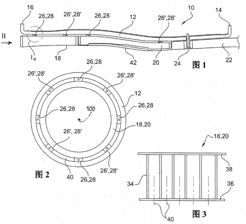
[0029] First refer to figure 1 , figure 1 Shown is a fan casing 10 of a turbomachine such as a turbojet or a propeller turbine, which belongs to the nacelle which encloses the engine of the turbomachine and inside which the fan rotates, which creates an auxiliary air flow, so Said auxiliary air flow flows between the nacelle and the engine, forming part of the thrust generated by the turbine.

[0030] The housing 10 comprises a generally cylindrical wall 12 comprising, at its longitudinal ends, fixed annular flanges 14, 16. The downstream flange 14 is fixed to the flange of the intermediate case (not shown) by screw-nut type means and the upstream flange 16 is fixed by screw-nut type means to the flange of the air intake in the nacelle (not shown). out).

[0031] The housing comprises sound-insulating annular panels 18, 20, 22 covering the cylindrical inner surface of the wall 12 and fixed to the same wall.

[0032] In the example shown, the wall 12 carries three annular p...


PUM


Abstract

Turbomachine casing (10) comprising a substantially cylindrical wall (12) and an annular one-piece acousting insulation panel (18, 20) mounted inside the wall, the panel comprising an annular surface that is radially external facing a radially internal annular surface of the wall, characterized in that the wall comprises on its internal angular surface first projecting members (28) which bear axially against second projecting members (26) belonging to the external annular surface of the panel and which are fixed to these second members in a dismantable manner.

Description

technical field [0001] The present invention relates to a turbine casing, and more particularly to a turbine such as a turbojet or turboprop in an aircraft. Background technique [0002] A fan case typically includes a generally cylindrical wall extending around a turbine fan blade, and an inner surface of the generally cylindrical wall is covered with an acoustic panel. Such panels typically comprise an annular honeycomb structure, the inner and outer surfaces of which are each covered with a skin which can have a plurality of perforations for improved noise attenuation. The perforations are intended to absorb the sound waves generated by the fans of the turbine. [0003] Acoustic panels of this type are described in the Applicant's previous applications EP-A1-2318679, EP-A1-2,088,290 and FR-A12965859. [0004] Acoustic panels in turbines are usually segmented, i.e. formed from several panel segments arranged end-to-end along the circumference and fixed to the casing wall...

Claims


Application Information

Patent Timeline
Patent Type & Authority Applications(China)
IPC IPC(8): F01D25/24B64D33/02F02K3/06F02C7/045
CPCY02T50/672B64D29/06F05D2250/283F02C7/045F01D25/246B64D2033/0206F02K3/06Y02T50/60F01D21/045F02C7/05B64D33/02F01D11/125F01D11/127F01D25/04F01D25/243F05D2260/96
Inventor 罗曼·普兰特罗曼·库隆杰弗洛伊·德 拉 夏佩尔保罗·福林弗洛伦特·罗宁
Owner SN DETUDE & DE CONSTR DE MOTEURS DAVIATION S N E C M A
Why Eureka
Try Eureka